61 KiB
Service Guide for Stellavox Sp 8
This Service Manual may be completed anytime in order to match possible modifications or variations. For necessary improvements we reserve all rights for required alterations without prior notice. Please consult us if necessary.
STELLAVOX 2068 Hauterive Switzerland
Phone : 038 33 42 33 Telex : 35380
ref.: 827
All care is given to ensure that the information provided in this booklet is accurate and up-to-date. Nevertheless progressive improvements may be incorporated in this equipment from time to time and this may lead sometimes to inaccuracies or inconsistencies in this publication.
We therefore suggest the cooperation of users in reporting such possible errors or omissions or even suggesting improvements.
For servicing, information and spare parts, please contact
STELLAVOX Jardillets 18 CH-2068 Hauterive Switzerland
IMPORTANT : please always quote equipment type and serial number when requesting spare parts or additional service information.
General
1.1 Technical Data
| Tape speeds | |
| Minimum battery voltage supply for | 76.2 cm/s (30 ips) = 24 V ext. |
| 38.1 cm/s (15 ips) < 15 V | |
| 19.05 cm/s (7.5 ips) < 13 V | |
| 9.5 cm/s (3.75 ips) < 13 V | |
| Tape slip for 13 cm spool | < 0.1 % |
| Tape spools | Cine max. 13 cm (5") |
| (with ABR accessory 30 cm (12") | |
| Sound height variation | |
| (DIN 45 507 : wow + flutter) | 38.1 cm/s (15 ips) < 0.06 |
| 19.05 cm/s (7.5 ips) < 0.09 % | |
| 9.5 cm/s (3.75 ips) < 0.12 % | |
| Starting time from setting: | at 9.5 cm/s 19 cm/s 38 cm/s |
| STOP to setting PLAY | ~ 1s |
| TEST to setting PLAY/RECORD | ~ 0.1s |
| (counter capstan locked in position) | |
| Wind-up time for 270 | 105 sec |
| Tape tension at 19 cm/s | 40 - 55 p |
| Current drain for average | at PLAY TEST REC. REWIND |
| winder diameter at 19 cm/s | ~= 100mA ~=55mA ~= 120mA ~= 130mA |
| (without additional accessory like | |
| SQS, SXQ, condenser mike, etc.) |
| Record channels with balanced micro-input: | |
| Frequency response | 30 - 20,000 Hz ± 1 dB |
| max. input level | 15 mv |
| max. sensitivity for 0 dB indicator | 0.2 mv |
| Noise (weighed) | < -124 dBm |
| Adjustable line inputs | |
| Frequency response max. | 30 - 20,000 Hz ± 2 dB |
| input sensitivity | 9V |
| Sensitivity for 0 dB-indicator | 30 mV |
| Input impedance | 10 kOhm |
| Unbalanced line output | |
| Frequency response | 40 - 20,000 Hz ± 1 dB |
| Output level | 1.55 V (max. 3.8 V) |
| Impedance (max. Load) | 200 Ohm |
| Headphone outputs | 15 - 2,000 Ohm |
| short circuit. protected, adjustable | |
| Balanced line output | |
| Frequency response | 40 - 20,000 Hz, ± 1 dB |
| Output level | 1.55/4.4 V (6/15 dBm) |
| max. Load | 200/600 Ohm |
| Automatic | |
| max. sensitivity | 0.2 mv |
| {for 0 dB-indicator) | |
| Compression ratio | 1:56 |
| Metering instruments | peak value indicator |
| Integration time | -10 ms at -1 dB |
| Battery test | 15 V at O dB indication |
| Equalization | CCIR or NAB |
| (will be fixed through | |
| headsblock electronics) |
1.2. Dimensions and weight
| Overall dimensions ( Height x Depth x Width) | 83 x 215 x 270 mm |
| (3.27 x 8.46 x 10.63") | |
| Gross weight with sound tape | |
| Case and batteries | 5.2 kg (11.5 lbs) |
| Net weight | 4 kg (8.8 lbs) |
1.3 Mechanical drawings
List No. 2b
Exchange of Assemblies
2.1 General
The STELLAVOX-magnetic tape recorder SP 8 possesses with its peculiar mechanical construction great mechanical stability. Base frames and deck plates are screwed, with solid distance pieces, lateral supply and front servicing area, into a torsionless casing. The rear distance pieces are terminal components for the direct battery compartments arranged here. At the side are the contact areas and less used service elements. At the front are the service area with operation switches, potentiometers and modulometers.
The deck plate carries on its top side the exchangeable sound headsblock. On the underside are, as mechanically separate units, the two wind on/off assemblies and the drive motor each fastened with three internal six-sided screws.
In the equipment are the electronic circuits as hermetically sealed plug modules.
Work on STELLAVOX magnetic tape recorders requires competent knowledge on the subject that has been completed in special training sessions. The following maintenance data should also help the less expert in sequence adjustment work to carry out and make clearer the mechanical and electrical combinations of the equipment.
If there are problems, consultation with our works or branches is possible.
In order to avoid short circuits during mechanical work in the equipment, the battery compartment should be emptied and the cable unplugged from the power supply. Trial runs while the apparatus is open should be carried out with great care and confined to the actual failure.
2.2 Sound Headsblock SHD
Work on the sound headsblock should be carried out with demagnetised tools. A screwdriver and special keys set are included in the delivery of the equipment or obtainable as a free part.
Open the tape path by putting the operation switch to "REWIND" for a short time. Further work should be carried out in position "STOP" so that no magnetisation of the heads will occur by replacing the SHD.
Lift off the head plate after removing the two sunk screw heads. The sound headsblock is fastened with three internal six-sided screws. In order to be able to pull the head upwards these should be lifted off. They are unforgettably arranged.
SHD are at first adjusted with the actual equipment and after they are optionally exchangeable.
After concluding the mechanical work the SHD should always be demagnetised.
2.3 Motor
To disassemble the motor, the pinch wheel lever must be removed. Unscrew lateral and top screws of that lever and remove it by pulling gently. Open the path as described in 2.2 and disconnect the equipment from any supply.
Remove the bottom plate and the drive-belts. Pull out the motor connector and its ground attachment.
Lie the equipment in front of you on a flat surface, held the motor firmly underneath with the left hand, unscrew the fastening screws on top with the key, put the equipment on edge, thereby holding the loose motor at an angle and raise the steel cable of the tensiometer over the gear of the mechanism. The motor can then be pulled out carefully.
To rebuild the laid out mechanism in its correct position, turn the motor pulley to the left. Hold the equipment at an angle, adjust the motor until the bracket of the mechanism arm interlocks into the counter-rotation arm still in the equipment. Thus with the left hand move the rotation arm until the interlock can be felt. Raise the cable of the tensiometer again over the gear and fasten the motor with the three inbus screws. Before the screws are tightened finally, test the mechanics.
For adjustment of the pinch wheel lever turn manually to the right the motor-pulley until the left roller arm pressed against it is in the working position "PLAY". Release the pinch roller (pull out button on the arm) and position roller arm at 0,2 mm distance from the capstan. Tighten both imbus screws of the arm. Press button, the counter-capstan roller is released and lies between 450-550 grams pressure against capstan.
After every dismantling and re-building of the motorblock, the tape tension rollers are set as described under 3.4.
2.4 Wind-off Side
Disconnect the equipment, remove bottom cover and belts, block brake and let the tensiometer cable hang out. Pull off filter module SIZ 8 and press the two blue capacitors against the SIZ~connector. Unscrew print plate SVC 48 and allow it to hang on the soldered cable.
Unscrew on the top the three imbus screws, which are all around the spool shaft, hold the unwind assembly with the left hand inside the equipment, and carefully pull it out.
Watch out for the position and direction of the steel cord. Further assembly in reversed sequence.
2.5 Wind-up Side
This winding assembly is in principle mounted like the wind off side. To disassemble, one unscrews the top side existing three imbus screws and at the same time with the left hand hold the winding section firmly, put the equipment on edge and pull it out.
The tensiometer cable is thereby lose and must re~assembly be first lead over the cable roller mounted in a rocker arm. The roller should at first point towards the loudspeaker. After that pull the cable over the second roller and the brass leaf spring and bring the winding section with a slight right turn into position and fasten.

2.6 Tape Tension Rollers
The rollers are supplied with their shaft. With this shaft the setting ring situated in the roller can be so turned that the two under 120° arranged fastening screws are accessible from the outside through the roller borehole.
To change the roller place the recorder with the narrower side towards one. Press roller with side opening outwards and unscrew the first of the two imbus screws. Pull out the key and turn the roller with the opening in the direction of the middle of the loudspeaker. In this position the second screw is accessible.

After loosening leave the key as it was in the screw; this facilitates the re-assembly.
Fasten new roller at 0.5 mm distance from the deckplate or with adjustment gauge for sound heads.
The stroboscope washer is self-adhesive and can be replaced, if pressed through with the shaft.
2.7 Steering Roller
The steering roller has a slightly convex twist and is provided with a ball bearing. To change, it shows itself as practical if the whole roller arm is taken off. Unscrew both screws and take off the arm. Insert new roller with shorter distance casing downwards and black marker points upwards. Assembly finished as described under 3.5

2.8 Pinch Roller
The roller is, as described in 2.7, exchangeable.
2.9 Connection Mountings
After removal of the labelled side panels on the left side of the recorder (6 imbus screws) the further fastening of the mounting is visible.
The work is easier to carry out, if the modules SPC + SOC are pulled out. On the right hand side of the apparatus there are two smaller panels, which after loosening their screws are accessible from both sides.
2.10 Main Switch
Remove all buttons: CH-1, CH-2, main switch, LINE-1, LINE-2, meter selector, undo all right two imbus screws of the modulometer and unscrew the four imbus screws in the front panel and take it off. The further fastening of the main switch is visible. Unsolder wires from the switch, undo fastening and pull out the switch inwards. Solder the new switch according to added sketch and finish further assembly in reverse sequence.
2.11 Potentiometer CH-1, CH-2
Remove the front panel as described in 2.10. The further fastening of the potentiometer is visible. Unsolder connection wires and pull out potentiometer inwards. The installation is easier if the motor is taken out previously.
2.12 Potentiometer LINE-1, LINE-2, SJK-Module
To change the line potentiometer, the SJK module must be disassembled. Remove buttons on the pre-attenuation switches, modulometer and its lighting. The SJK module is fastened inside screws and under the modulometer with two further sunk headed screws.
The two line potentiometers are mounted with central fastening on a U-form metal component. This metal component is fastened at the front with two sunk headed screws. Unsolder connections of the potentiometers before their removal. Assembly in reverse order.
2.13 Potentiometer "PHONE"
Remove button of the potentiometer, undo fastening of the side panel (4 screws) and pull this off..The potentiometer is now accessible from both sides. Unsolder wires and undo fastening nut. Complete assembly in reverse order.
2.14 Potentiometer "Loudspeaker"
Remove front panel as described under 2.10. Take off button of the potentiometer, the fastening of the potentiometer, unscrew 2 sunk headed screws at the front between the channel potentiometers, unsolder wires and take out potentiometer inwards. Further assembly in reversed order.
2.15 Switch "TAPE/DIRECT"
Remove front panel as described under 2.10. Unscrew the bottom cover and disassemble motor. Undo holding piece for push buttons "BATT., LIGHT" and the switch. Unscrew central fastening of the push buttons with special key and unsolder the switch on the inside on the plate 0148. Take out the holding piece with push buttons and switch forwards. Assembly in reverse order.
2.16 Switch "SPEECH/MUSIC"
Unscrew ‘side panel as under 2.9 and bottom cover. The further fastening of the switches is visible. Unsolder connection wire and pull out switch inwards. Assemble in reverse sequence.
2.17 Switch "MONO-STEREO"
Remove bottom cover, pull out side modules SPC+SOC. The switch is soldered on a print plate situated behind the plug modules. Unsolder print, take out and change switch. Assembly in reverse sequence.
2.18 Switch "METER"
Remove the bottom plate and the front panel as described under 2.10. Dismantle the SJK module as described under 2.12. Undo holder-piece for switch and indicator at the front. Unscrew potentiometer support and remove holder depart with indicator forwards. The switch is now freely accessible. Assemble in reverse order.
2.19 Switch "Speed"
Unscrew the bottom cover and the side panel. Undo button and fastening piece for the switch. Central fastening and soldered joints are now freely accessible for further work. Assembly in reverse order.
2.20 Switch "Play"
Remove the bottom cover and unsolder connection wires of the switch. Remove central fastening with special key and pull out switch inwards. Assembly in reverse sequence,
2.21 Pre-Attenuation Switches, Supply Switches
These switches are part of the SJK-module. The dis-assembly of this module is described in 2.12, Unsolder module, take out and solder to changed component. Assembly in reverse sequence.
2.22 Push Buttons "BATT., LIGHT"
The push buttons can be changed according to 2.15
2.23 Modulometer
Remove the modulometer cover after undoing the 4 inbus screws and pull out the instrument. Unsolder wires and change instruments. Assembly in reverse sequence. Be sure that the longer angled modulometer cover side is mounted on the edge side of the machine.
2.24 INDICATOR "PILOT"
Undo front fastening with special key and pull out instrument forwards. Cut lead and solder on new instrument with shortened lead, insulate this and install instrument.
2.25 Loudspeaker
Remove bottom cover and take off plug module SQS (SXQ) and SIZ. Dismantle wind off assembly and transformer set SOT, respectively dismantle their support with 48V-DC converter. Undo loudspeaker fastening 3 screws on the top, unsolder connection wires and take out loudspeaker inwards. Assembly in reverse sequence.
2.26 Modules
The modules are for most part plug units exchangeable in the described way. Some possess an additional ground-wire which has to be unsoldered. The changing of the SJK-module is described under 2.12, and that of the output carry over set SOT under 2.25.
Mechanical Adjustments
3.1 Headsblock SHD
Every sound head carrier is equipped with 3 or 4 heads for erase, record, pilot and play-black. The individual heads, in a cutaway mounting, are adjustable from the opened SHD with 4 thread screws. Two screws in the shaft form the edge, with which at the same time head height and zenit is adjusted. Two further screws sideways from the slit serve the adjustment of the azimut and the fixing of the heads.

The following work described requires a trained technician. The following special tools and aids are necessary:
- Level plate, cut and polished
- Adjustment gauge for sound heads
- Magnifying glass 8 x
- Diamond paste 16 μ and 8 μ
Put sound head carrier on the flat plate and test whether base is absolutely even. Remove carefully possible impurities or rub down evenly with a flat plate covered with a very fine emery paper.
With adjustment gauge, test the Height, Zenit and Azimut of the heads: if necessary adjust. Use magnifying glass and repeat the foregoing adjustments until the necessary accuracy is achieved,
Fix the SHD with heads up and even up the surface of all heads with diamond paste 16 and polish with the diamond paste 8.
Use dull back of a magnetic tape, on which some diamond paste is spread. Pull tape around the head backwards and forwards about 10 times. Clean the heads carefully with cotton wool and alcohol and test the quality of the air gaps with the magnifying glass. Finally demagnetise heads.
3.2 Lever Mechanics of the Motor
Stellavox magnetic tape recorders SP 8 are provided with a lever mechanism set in motion by motor. It is switched on and off with reversed motor direction.
On its circuit one partially toothed brass disk is connected over a lever mechanism with the pinch roller arm and moves it after each rotation of the motor against the SHD or the tape channel will be opened.
A small Delrin toothed wheel, positioned on a movable lever, is actuated by a gear on the motor shaft. It propels the partially toothed brass disk until it stops at the respective ends of the gearing. The end positions will be held stationary.
Through vigorous action on the pinch roller arm which should never actuated Manually, the Delrin gear can be damaged.
Changing of the Delrin gear:
Remove the SHD, unscrew the three imbus screws on top side of the capstan bearing and pull it off. Undo lever with gear bearing, remove and change gear.
Adjust 0,2 mm between gear and bearing and screw up the moving lever with the gear bearing tightly. Assemble in reverse sequence.
Beginning and end of the brass toothed disc are adjustable. In conjunction with the action of the steel round springs the engagement and release of the intermediate toothed wheel can be adjusted.
By toothed brass disk on the left stroke, must engage the Delrin-gear on its return without sticking. On the opposite side the gear should engage with negligible amount. Wrong adjustment results in gear noise through jamming or the gear does not engage.

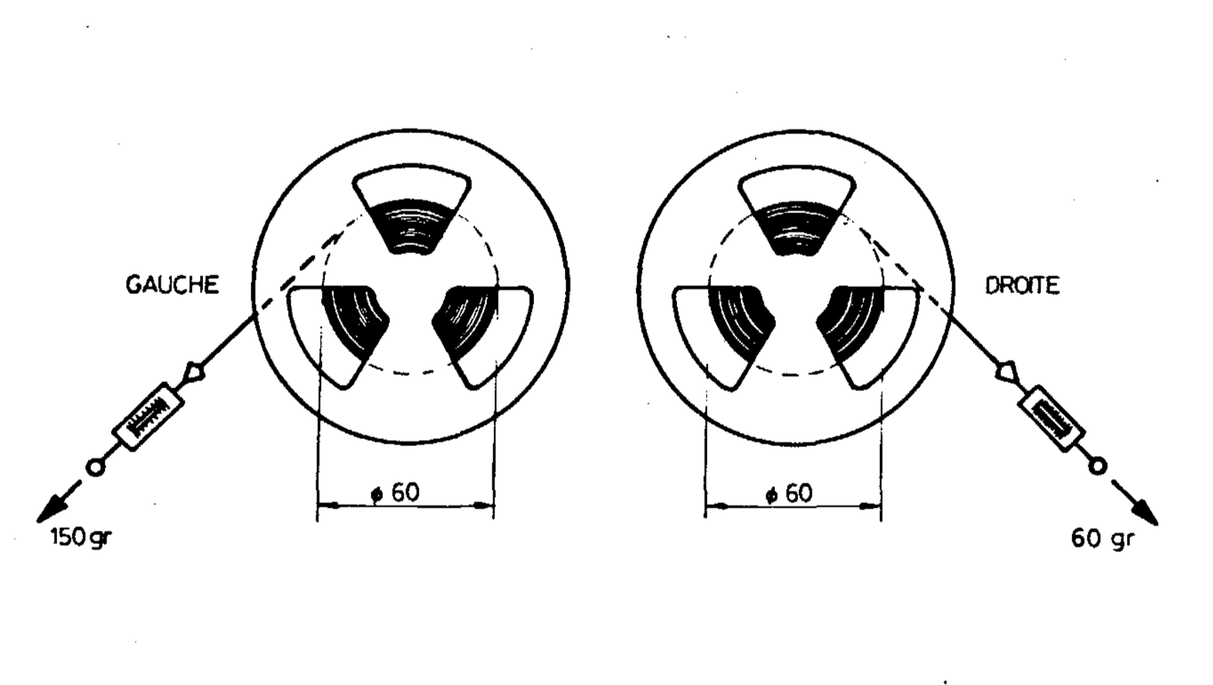
3.3 Brakes
The brake action of the completed winding assemblies may be tested for the average coil diameter with a spring balance.
Put on a 1.5 m magnetic tape on a spool with 60 mm diameter, suspend tape beginning in a spring balance and at the same time draw out the tape in one movement. The measured value for the unwinding assembly must amount to 150 g, and for the winding up assembly 60 g. Tolerance +/- 25%.
By varying amounts the block brakes of the unwinding assembly can be covered with a new, self-adhesive piece of felt. For the winding up assembly side round pieces of felt are also obtainable as spare parts.
Any further defects will be corrected by the works repair shop.
3.4 Tape Tension
The tape tension is adjustable for both rewind and take-up assemblies. Unscrew base cover. The cable tension adjustment is as imbus-screws for the rewind section just beside the SIZ-module, that for the take-up assembly near the STF-module.
First adjust the take-up side. Divide tape of 13 cm diameter spools equally on both reels and lay the recorder vertically on 15 battery-container side. Using the imbus screwdriver (or imbus—key) rotate the small drum retaining the cable so that the tape tension roller, at 19 cm/s tape speed, releases 4 mm of the top side visible slit to the right.
On the rewind side the adjustment is correct when the slit is symmetrically covered by the left tape tension roller.
IMPORTANT: Both drums are secured with two screws which should be lightly unscrewed before adjusting the drums. Re-tighten these screws after the adjustment. With these adjustment a constant tape tension of about 40 ~ 55 g is automatically guaranteed.
3.5 Steering Roller
The slightly convex turned roller provides with its ball bearing for accurate tape running and flutter damping. It is changeable after loosening the imbus screw on the top of theroller. For correct positioning of the roller lever, fix it in opened position with 30 mm distance to the deck plate edge.

3.6 Pinch Roller
The adjustment of the pinch roller is described under 2.3.
3.7 Bearings
The ball bearings of the flutter and pinch roller as take-up assemblies are replaceable by skilled customers. Other bearings can only be pressed in at the factory.
To change the ball bearing in the flutter or pinch rollers, remove the brass disc which is fastened with three screws and change bearing. Assemble in reverse sequence.
To change the two ball bearings in the take-up assembly, remove the rocker-arm. The shaft is locked with an imbus screw. Take out disc brake with 6 red pieces of felt. The locking-friction disc situated-underneath on the shaft is unscrewable after loosening its screw. Pull out shaft, remove brass distance tube, spring washer and bearing. Change bearing and replace spring washer and tube.
On the other side of the take-up unscrew the 3 screws, remove with brass leaf spring and knock out bearing. Change bearing and screw up. Insert shaft with distance tube and lock friction screw. Put spiral spring in the hole, apply brake disc, put in rocker arm with shaft and lock with imbus screw. The section is again ready for fitting.
3.8 Lubrication Prints
All ball bearings are oiled once for their life and require no further maintenance.
The upper capstan bearing can be occasionally oiled afterwards, solely with fine machine oil.
Should the brass leaf spring on the take-up assembly be changed, oil the surface between steel cable and spring with resin free oil.
Circuits of the Drive Assembly
4.1 General
The driving force of the STELLAVOX-magnetic tape recorder SP 8 is a Stellavox servo-regulated direct current motor. The use of Samarium-cobalt for the stator as well as the special patented flat rotor are responsible for the high efficiency of the motor.
The disc Shaped armature carries an axial commutator and a tachodise on its perimeter produces 400 bright-dark sectors, for the opto-electronic control range.
The current is supplied over 6 brushes.
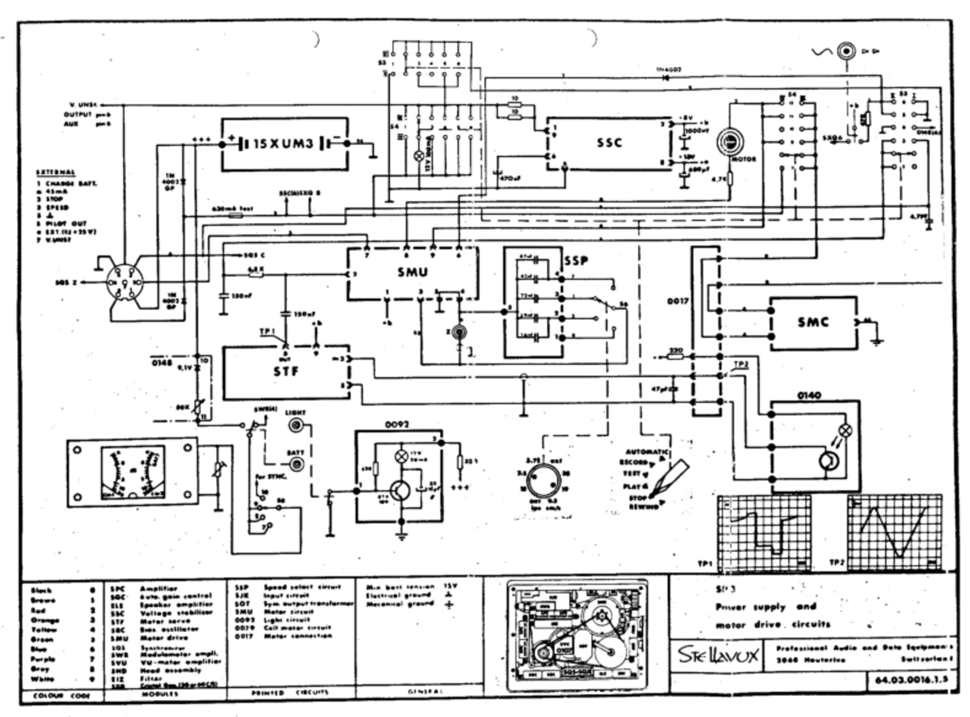
For the stabilised forward running on record and play-back (without synchroniser operation) the following modules and circuits operate: Voltage stabiliser SSC + 8V, circuit 140, tacho-module STF, circuit speed selector for SSP, motor drive module SMU and the motor SMC.
In the function PLAYBACK synchroniser operation is possible with the internal module SQS or an external instrument. This has additional effect on the operating point of the motor driving module SMU.
To rewind the tape, the motor receives the maximum battery (or from power supply (voltage with reversed polarity and unregulated over the operation switch. For details see drawing No. 64.03.0016.1.5.
4.2 Power Supply
| Operating function | |
|---|---|
| PLAYBACK | Fuse 630 mA+, S4 IV(3)S3 V(3), motor. |
| Ground (-), point 5, SMU, point 9, S4 IV(9), motor. | |
| RECORD | Fuse 630 mA+, S4 IV(5)S V (5), motor. |
| Ground (-), point 5, SMU, point 9, S4 Iv(11), motor. | |
| AUTOMATIC | Fuse 630 mA+, S4 IV(6), motor. |
| Ground (-), point 5, SMU, point 9, S4 IV(12), motor. | |
| REWIND | Fuse 630 mA+, S4 IV(7), motor (reversed polarity). |
4.3 Motor Speed Control
The rotation of the motor armature produces over the phototransistor in the circuit 0140 a sinusoidal current of 30 - 200 mV/3,2 kHz at 19 m/s tape speed. The STF-circuit amplifies this weak signal, making it independent from AM, and delivering a strong squared signal to the SMU-module.
Circuit: OV (-), phototransistor circuit 0140, STF module Point 2 (in), Point 8 (out), C 150 nF, to SMU.
The frequency reference of the SMU (discriminator) compares to the STF frequency and delivers a servo controlled current to the motor in order to maintain its speed constant, independently of the supply voltage and the mechanical load. .
Circuit: STF module Point 8, C 150 nF, to 6,8 kOhm, SMU module Point 2.
Motor: o V (-), SMU Point 5, Point 9, S4 IV (9,11,12), Motor SMC, S3 V (3,5,6), S4 IV (1,3,…6), fuse 630 mA, +.
4.4 Speed switch
The SSP switches different capacitors to produce, for the discriminator in the SMU module, resonance frequencies of 1.6 kHz = 9,5 cm/s, 3,2 kHz = 19,05 em/s and 6.4 kHz = 38 cm/s tape speeds.
Circuit: OV (-), SMU Point 5, Point 4, SSP Point 5, Point 3.
4.5 Remote Control
The Z-coax. socket allows the remote START/STOP. The remote control only applies to the running of the motor. With shortened contacts of the socket, the motor stays still. In position EXT. of the speed switch a speed variation of 10 % is possible in connection with the remote control point ASV 8 (for 19 cm/s).
4.6 Forward wind
Operation of the push button F.F. shortens (SMU Point 6) the motor regulation. The motor runs at a maximum unregulated speed according to the supply voltage.
Electrical Drive Assembly Adjustments
5.1 General
Through the use of encapsulated preadjusted circuits and amplifier modules no more adjustment of the drive electronics is necessary, apart the vernier adjustment of the tape speed made by the core attainable with a small screwdriver over the hole of the SMU module.
5.2 Stabilised speeds running
Speed-selection switch SSP and motor drive module SMU form among other thin; together a LC-link, as frequency-determining part of an oscillator circuit, from which the maintenance of the speed of rotation of the motor depends. Inductance and capacity of the LC-link are variable for the speed selection and vernier adjustment.
The 4-step rotary switch controls the tape speeds 9.5/19/38 cm/s by matched capacities. In position EXT., the Z-socket provides for the external connection of a condensor or the remote control unit ASV 8. .
The motor SMU module has a small opening, through which the variable ferrite core of a spool is accessible.
For the fine adjustment of the speed unscrew the concealed screw on the right side panel, Through the opening one can vary the ferrite core, with a small screwdriver,
The fine speed adjustment is effected on running tape by checking the stroboscope disk of the tape tension roller. The strobe disk must be illuminated with fluorescent light.
5.3 Brushes
The motor is provided with a 6-part brush holder, which picks up 3 pairs of commutator brushes. For running two opposite brushes are necessary. The three pairs increase the reliability.
Switch off batteries or power supplies and remove the base cover. Take off belts and take out insulation disc fastened with three screws on the brush holder. Unsolder brushes - wires and take off insulation mantle. Lift the spring pressed against it with tweezers and pull the brushes out of the holder. Care must be taker, that the wire to the brushes leads through under the spring without mechanical strain, Thereby a reaction on the brush mounting and a noise free running of the motor will be guaranteed.
One of the three pairs of brushes is made of some dark material for better compatibility between the metal of the commutator and the remaining brushes. These brushes are identified by a coloured point on the brush-holder.
See also Stellinform 7807.10/T of 14.7.1978.
5.4 Opto-electronical-Tacho System
The opto-system consists of 400 black-white lines on the perimeter of the armature, the lighting installation, and the optical sensor with photo- transistor.The whole unit is plugged in and locked on the side of the motor housing.
Maintenance and adjustment work is limited to the cleaning of the individual parts. It is advisable to “lean the optical parts regularly with great care. In the case of defect replace the whole unit.
5.5 Control Measurements
Allow motor to run in position EXT. of the speed rotary switch with 12 v voltage, loosen three cylinder head screws on the edge of the stator and adjust be turning the brush holder on minimum current input. Tighten screws again.
Circuits of the Amplifier Electronics
6.1. General
The amplifier electronics consists of exchangeable plug-in modules. By use of a mono headsblock switch over to "Mono" with the screwdriver-rotating switch located on the left-hand panel.
On play-back one gets two separate identical independent mono signals.
For both record and play-back channels, plug-in modules of one type SPC + SOC are used. A built-in loudspeaker with final stage SLE B monitors the two channels. Similarly the signals are measured by a double modulometer controlled by the SWR unit.
The SJK-module has two adjustable, symmetrical microphone inputs with all supplies for condensor microphones, two adjustable line inputs, two non- adjustable line inputs and to the left channel a 1 kHz clapper oscillator. The clapper oscillator is part of a synchroniser module.
In position RECORD the bias oscillator is activated, as in position AUTOMATIC the compressor SGC.
The pilot channel is fitted with a combi-head, for which the signal through the synchroniser module can be generated or amplified.
Both main asymmetrical outputs may be switched (front panel switch) to "Tape" or “Direct” control. The headphone jack is located on the right-hand panel with its own control. An optical plug-in module SOT may be installed inside the SP 8 for balanced outputs.
6.2 Current Supply
The audio-modules are supplied from the voltage stabiliser SSC with a stabilised voltage of 13 V.
In the operation positions "PLAYBACK, TEST, RECORD and AUTOMATIC" the voltage stabiliser maintains its current supply: S 630 mA+, S4 Contacts IV (1), Iv (3)…IV (6), Point 1/9 SSC. Ground (-), Point 5 SSC.
In the operation position "RECORD" and "AUTOMATIC" the bias oscillator and the clapper generator maintain their negative potential for ground (-), $ 2 Contact VIII (5) or VIII (6). Point 5 SBC, respectively, Point 7 SXQ.
6.3 Play: Drawing No. 64.03.0019.1.5
The circuit is described as single channel. On mono-operation the first amplifier stage of SPC module is connected to sound head carrier Point 2 on OV Sh (circuit of the SHD). See circuit No. 64.03.0018.1.5
SHD, sound head play-back, Point 11, C 6,8 uF, Filter SIZ, SPC + SOC CH-1 Point 2 (in 1), SI IX (1,2,3) R 10 kOhm, C 6,8 uF, SPC + SOC Point 6 (in 2), Point 8 (out 2), C 220 uF, Point 6 switch TAPE/DIRECT, SWR, Point 2 output socket.
Filter SIZ: See circuit No. 64.06.0009.6.0.
Sl IX (3), Pot. CH+1 10 kOhm, R 6,8 k, C 6,8 uF, SPC + SOC Rec. CH-1 Point 6 (in 2), Point 8 (out 2), C 1000 uF, SGC, SOT, Point 7 switch TAPE/DIRECT.
SWR: SWR Point 7 (in 1).
Over C 6,8 pF on Point 6 (in 2) of the rec.-module SPC + SOC, the modulations of AUX LINE and MIXER are introduced.
6.4 Test: Drawing No. 64.03.0018.1.5
The circuit is described as single channel.
Input Micro 1, $3k-module Point 1 (in 1), Point 6 (out 1), Switch Speech/ Music, SPC + SOC module Rec. CH-1 Point 2 (in 1), Point 4 (out 1), SGC, SI IV (4), Pot. 10 kOhm, R 6,8 kOhm, AUX input, C 6,8 uF, Point 6 (in 2), Point 8 (out 2), 1000 uF, C 6,8 uF, 470 Ohm, SIZ-module Point 1 Point 2, SHD, S 2 VIII (4), OV.
SGC: Point 6, Point 7 SGC-module. . .
AUX input: LINE 1, Point 1 Bu AUX, Pot 10 kOhm, Print 0085 Point 1, R 12 kOhm, Point 3, 680 kOhm. Over this resistance the MIXER-input is decoupled.
1000 pF: Here the signal supplies balanced the output amplifiers SOT over the switch TAPE/DIRECT Point 7 and 1 to Bu output and to SWR module Point 7 (in 1) and ‘to SGC module Point 2 (in 1).
See circuit No. 64.03.0018.1.5
6.5 Record: Drawing No. 64.03.0018.1.5
In position RECORD of the operation switch the functions undergo the operation TEST with the following difference: SHD (Sh 6,4): the short circuit over 5 2 VITI (4) is lifted. Over S 2 VIII (5) the bias-oscillator SBC and synchronizer module SXQ receive negative potential and work.
See circuit No. 64.03.0018.1.5
6.6 Automatic: Drawing No. 64.03.0018.1.5
Possible internal rewiring of the STELLAVOX SP 8 results in two various operations at the AUTOMATIC: 1. manual adjustment of a higher gauge threshold with the potentiometers CH-1 and CH-2: at higher levels, the SGC-module acts on the feedback of the SPC-amplifiers. 2. the manual adjustment of the channel potentiometer will be replaced by a fixed resistor which corresponds to the value of the work setting of the potentiometer.
Description 2: detection over. 1000 pF, R 56 kOhm, SGC module Point 2 (in 1) SPC + SOC module Point 4 (out 1), S 1 IX (6), Pot. 10 kOhm R 6,8 kOhm 6,8 pF, Point 6 (in 2). Feedback: SPC-+ SOC Point 4, SGC Point 6, Point 7, SPC + SOC Point 3 (FB 1).
See circuit No. 64.03.0018.1.5
6.7 Tape/Direct
The functions of that switch are described under section 6.3 to 6.7
Recent equipment possess a relay, which lies in position TEST of the main switch at Point 6 of the "Tape-Direct" switch.
6.8 Mono/Stereo
Printed platé-6085 Points 3 and 4 are connected together on MONO. The adjustment of the feedback at.the points 7 (FB 2) (resistor between 4 and 5) of both modules SPC + SOC is used to match their levels.
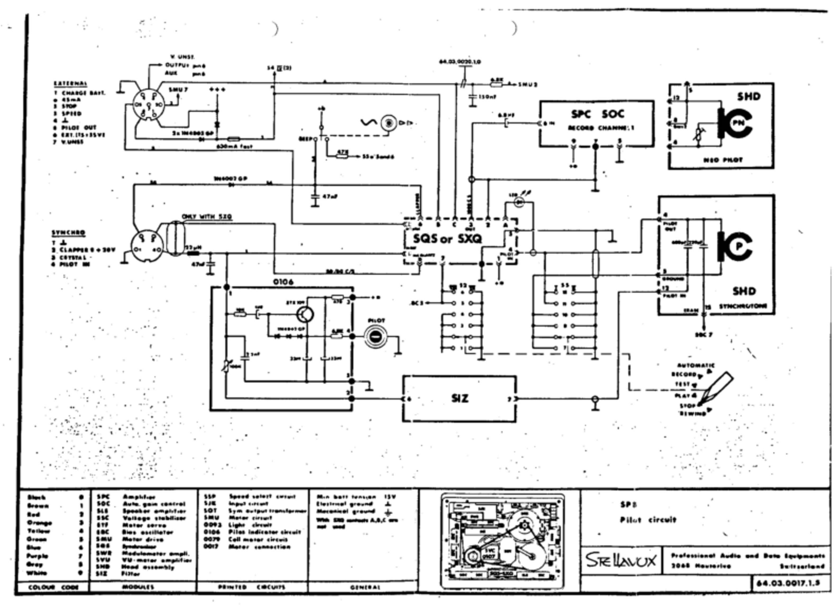
6.9 Start Marking: Drawing No. 64.03.0017.1.5
Operating the button "Beep", switches the 1 kHz-oscillator on.
Circuit: +b, button "Beep", synchrosocket, SQS or SXQ-module Point 6, circuit oscillator, Point 2, 0 V. External release is also possible over Point 2 of the synchrosocket, Diode IN 4002 GP,
LF-track: Synchromodule Point 3, C 6,8 uF, SPC + SOC module (Rec.) Point 6.
See circuit No. 64.03.0017.1.5
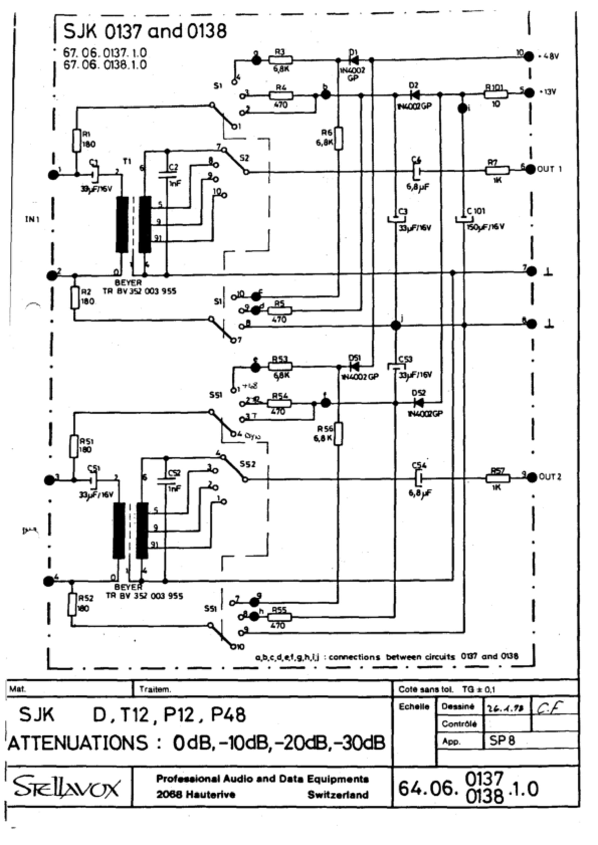
6.10 Condensor Microphone-Supplies: Drawing No. 64.06.0138.1.0
Consider primary of the transformer: The A/B-circuit is decoupled with two 180 oHm resistors. They are connected to a 2-channel, 4=steps switch.
- Current-free operation for dynamic microphone: the switch is open.
- Parallel-fed charge 12 volt (T 12): +13 V, SJK module Point 5, R 10 Ohm, CH-2, C 150 pF, Diode D2, C 33 RF, Sl Contact 2, R 180 Ohm, Point 1. QO Volt, SJK module Point 8, Sl contact 8, R 180 Ohm, Point 2.
- Phantom supply 12.Volt (P 12): From the Diode D2, the positive is connected to each R 470 Ohm on the contacts 3 and 9 of the step switch.
- Phantom supply 48 Volt (P 47): +48 V, SJK module Point 19, Diode D1, branching out on resistors 6,8 kOhm, contact 4 and 10 of the step switch, resistors 180 Ohm, A/B circuit.
See circuit No. 64.06.0138.1.0
6.11 Pre-Attenuations
Secondary of the transformer: three tappings give attenuations 10/20/30 dB, which are connected to the 4-step switch. Out 1, SJK module Point 6, R1 kOhm, C 6,8 pF, S2 contact 7/8/39/10 S2, transformer, Point 7,0 V.
6.12 Pilot Sound Recording with Cable — Drawing No. 64.03.0017.1.5
Synchrosocket pin 4, inductance 22 uH, SQS or SXQ module Point 8 (in Ref.). Behind the inductance is a line to the circuit 0106 Point 1, Pot. 100 kOhm, Point 2, SI2Z-module Point 6 and 7, SHD Point 12 (pilot in).
The meter "PILOT" receives its voltage from point 4 of print 0106.
6.13 Pilot Sound Recording with Internal Crystal Generator
The Point D of the synchronisers SQS or SXQ feeds the 50 Hz crystal pilot tone signal, joined to pin 3 of the synchrosocket. Through an external bridging plug the signal (6.12) reaches pin 4 or a wire bridge may be inserted.
6.14 Pilot Play-Back
Pilot sound head SHD Point 4, synchromodule Point 4 (PILOT IN) Point Z (PILOT OUT), external socket pin 5.
6.15 Synchroniser Operation: Drawing No. 64.03.0017.1.5
- With internal reference: SQS module Point D (OUT crystal), synchrosock: pin 3, bridging plug, pin 4, inductance 22 pH, SQS module Point 8 (IN Ref).
- With external reference: the external reference signal must be put on at pin 4 of the synchrosocket, which follows then the path as above.
6.16 Loudspeaker/Headphones —. Drawing No. 64.03.0019.1.5
Out from the print 0148 (TAPE/DIRECT) of the switch "Tape-direct", the signals for the single-channel and amplifier SLE C will be uncoupled over 10 K resistors. A 10 kOhm potential is wired between. Headphones can be u om between pins 1 and 5, or on the jack. Print 0148, Point 1, SWR. output socket pin 2, 100 Ohm, inductance 1 mH, pin 1 (fixed level), Pot. 1 kOhm, jack.
Settings for Recording and Playback
7.1 General
The system interchangeable plug-in sound heads-block implies the equalization in the SHD itself. The setting parts are variable or fixed resistors and condensors.
An increase in the capacity value causes a decrease in voltage. The oscillator frequency lowers with rising capacity values.
7.2 Average values
(according to tape brand, tape speed and standard)
| MONO | |||
|---|---|---|---|
| Playback level | 1 kHz | C1 | 30 ÷ 40 nF |
| Playback level | 10 kHz | R1 | 470 Ohm ÷ 5 kOhm |
| Playback level | 50 kHz | R2 | 120 k ÷ 470 k |
| Record level | 1 kHz | R3 | 1k ÷ 1.8k |
| Record level | 10 kHz | C2 | 10 nF ÷ 30 nF |
| Oscillator frequency | 61,44 kHz | C4 | 1 nF ÷ 2 nF |
| Bias level | C3 | 1.8 nF ÷ 3 nF | |
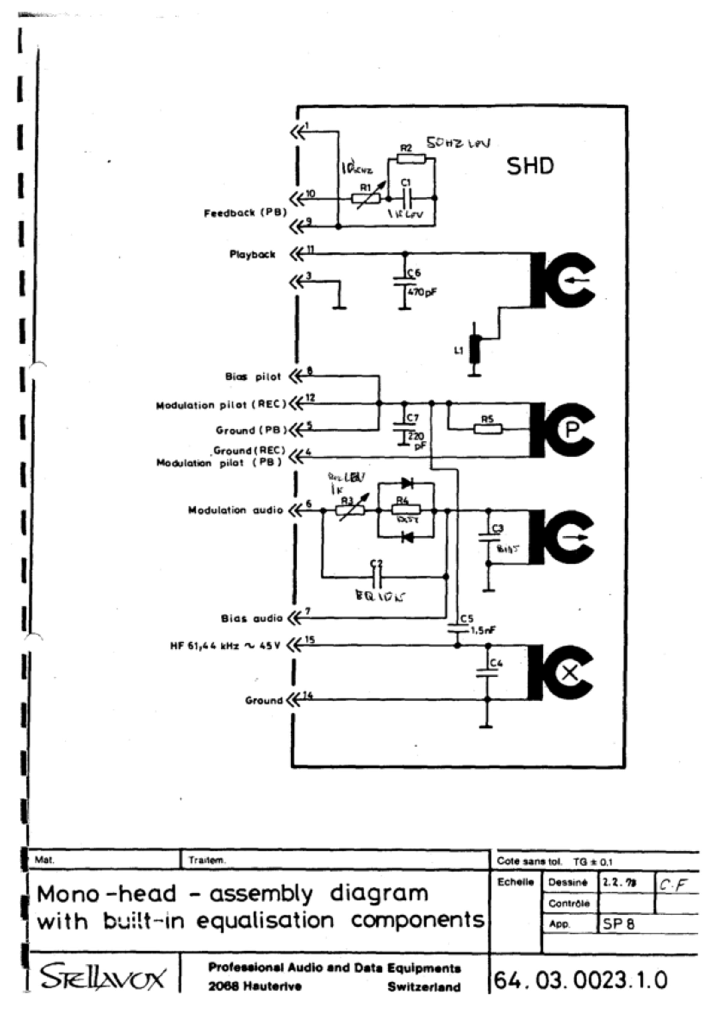
| Distortion compensation | |||
| (drawing No. 64.03.0023.1,0) |
| STEREO | |||
|---|---|---|---|
| CH1 | |||
| Playback level | 1 kHz | C1 | 28 ÷ 32 nF |
| Playback level | 10 kHz | R1 | 820 ÷ 5 k |
| Playback level | 50 kHz | R2 | 120 ÷ 470 k |
| CH2 | |||
| Playback level | 1 kHz | C51 | 28 ÷ 32 nF |
| Playback level | 10 kHz | R51 | 820 ÷ 5 k |
| Playback level | 50 kHz | R52 | 120 ÷ 470 k |
| CH1 | |||
| Record level | 1 kHz | R3 | 1.8 ÷ 3.3k |
| Record level | 10 kHz | C2 | 2.2 ÷ 22 nF |
| CH2 | |||
| Record level | 1 kHz | R53 | 1.8 ÷ 3.3k |
| Record level | 10 kHz | C52 | 2.2 ÷ 22 nF |
| Oscillator frequency | C4 | 1 ÷ 2 nF | |
| Bias level | CH1 | C3 | 2.2 ÷ 4.7 nF |
| Bias level | CH2 | C53 | 2.2 ÷ 4.7 nF |
| (drawing No, 64.03.0022.1.0) |
| NEOPILOT AND SYNCHROTONE | |
|---|---|
| Play-back level with SxQ 023 | R6 (Drawing No. 64.06.0091.1.9) |
| Play~back level with SxQ 123 | R6 (Drawing No. 64,06.0091.0) |
| Play-back level with SQS | R8 (Drawing No. 64.06.0115.1.07) |
| Record level | R1 (Drawing No. 64,03.0017.3.0) |
| Neopilot-symmetry | R5 100k infinite (Drawing No. 64.03.0023.1.0) |
7.3 Adjustment of the Sound Head Carrier
7.4 Measuring Equipment and Aids
| Demagnetizer | Reference Tapes |
| LF-Millivoltmeter and valve voltmeter | R-Eliminator |
| LF-Generator | C-Eliminator |
| Distortion Analyzer | Headphones |
| 2-Beam Oscilloscope | DC-Adjustable supply |
| Digital Counter | Soldering Iron and components |
| Flutter-Meter | according parts lists |
7.5 Playback Setting
Demagnetise sound headsblock and capstan. Put on reference tape according to selected speed. Connect LF-millivoltmeter and oscilloscope with the outputs of the equipment: "OUTPUT DIRECT 1" = Point 2 and Point 3 or “OUTPUT DIRECT 2" = Point 4 and Point 3 of the output socket. Put switch "TAPE/ DIRECT" in position "TAPE". For two speeds headblocks, the above should be repeated.

7.6 Gap Setting for Mono
Put on reference tape "Gap setting 10 kHz" and switch equipment to "PLAY". With adjustment screws on play-back head, set maximum level.
7.7 Level 19 cm/s (320 nWb/m)
Put on reference tape "Operating Level 100L Hz" and switch equipment to PLA Adjust with Cl output level on 1.55 V (+6 dBm).

7.8 Frequency Play
Put on reference tape "frequencies" and switch equipment to PLAY. Adjust with Rl at 12 kHz on O dB deviation. Adjust with R2 at 60 Hz on -1 dB. Adjust with Cl at 1 kHz on O dB. Attention: this section of the reference tape is normally at ~20 dB!
7.9 Gap Setting on Stereo
Put on reference tape "Gap setting 10 kHz" and switch equipment to PLAY. Adjust with adjustment screws on play-back head on minimum phase angle. (Use double trace scope).
7.10 Record Settings
Connect equipment as 7.5 and sound generator with inputs of the equipment: "AUX LINE 1" = Point 1 and Point 3 or "AUX LINE 2" = Point 2 and Point 3 of the socket.

7.11 Oscillator Frequency
Connect digital counter (high input impedance!) on Point 15 of the headsblock. Put on erased tape and switch equipment on "RECORD". Set with C4 oscillator frequency on f = 61.44 kHz. Adjust voltage with valve meter (high input impedance!).

7.12 Gap Settings on Mono
Set sound generator on 10 dB under reference tape (1.55 V) and 10 kHz. Put on erased tape and switch equipment on RECORD. Set with adjustment screws on record head for maximum level.
7.13 Pre-Magnetisation
Set sound generator on 10 dB under reference level at 10 kHz. Unsolder condensor C3 at hot end. Connect capacity eliminator box. Put on empty tape of type used, switch equipment on "RECORD" and switch "TAPE/DIRECT" on "TAPE". Set the pre-magnetisation with capacity for maximum

7.14 Level
Set sound generator on reference level (1.55 V) and 1 kHz. Put on empty tape of the type used, switch equipment on "RECORD" and switch "TAPE/DIRECT" on "TAPE", Set with R3 output level on 1.55 V.
7.15 Frequency play over tape
Set sound generator on 10 dB under reference. Put on empty tape of the type used, switch equipment on RECORD and switch "TAPE/DIRECT" on "TAPE". Set with C2 for 0 dB deviation. If necessary, correct with R3 as required on 1 kHz.
7.16 Distortion Compensation
Set sound generator on level 10 dBm (= 2,5 V) and 1 kHz. Put on empty tape of the make used, switch equipment on RECORD and switch "TAPE/DIRECT" on "TAPE", Set with R4 on minimum distortion, and check for low distortion also at lower levels.

7.17 Gap Setting of Pilot Sound Head
Put on measuring tape "Sound record 1 kHz reference level". Connect LF—millivoltmeter and oscilloscope with the pilot sound output of the equipment ("PILOT OUT" Point 5 and Point 4 of the "EXTERNAL" socket). Set with adjustment screws on pilot sound head on minimum residual level.

7.18 Playback Level "PILOT"
Put on measuring tape "Sound record 1 kHz reference level". Connect LF—millivoltmeter and oscilloscope with the pilot sound output of the equipment ("PILOT OUT" Point 5 and Point 4 of the "EXTERNAL" socket). Set with adjustment screws on pilot sound head on minimum residual level.
Put on reference tape "Pilot record 50 Hz, reference level" and switch equipment to "PLAY". Set output-level with R6 by use of SXQ 23 or SXQ 123; and with R& by use of SQS on 1.55 V.

7.19 Record Level "PILOT EXTERN"
Set sound generator on reference level 1.55 V and 50 Hz and connect with the synchrosocket "PILOT IN" Point 4 and Point 1. Put on empty tape and switch equipment on RECORD. Correct with R1 record level so that the playback level (see 7.17) amounts to 1.55 V in position "PLAY",

7.20 Record Level "CRYSTAL PILOT"
First carry out work under 7.18. Adjust the 50/60 Hz signal with R 10 by use of SXQ 123 and with R14 by use of SQS, so that the playback level amounts to 1.55 V.

7.21 Cross-talk from Sound to Pilot
Put on reference tape "Sound record 50 Hz, center erased" and switch equipment to "PLAY". Connect millivoltmeter and oscilloscope as under 7.16. The measured level must lie < 14 dB under the LF-operating level. Anyway, the synchroniser SQS operates correctly with up to -12 dB rejection.
7.22 Cross Talk From Pilot to Sound
Set and connect sound generator as in 7.18. Put on empty tape and switch equipment on "RECORD". Switch "TAPE/DIRECT" on "TAPE",
Connect LF-voltmeter and oscilloscope as in 7.4. Set with R5 (Drawing No. 00.0006.1.0) for minimum rejection of the pilot into the sound channel which should not be higher than 2 dB above the tape noise of the pilot signal. The value of the cross-talk attenuation will be influenced by the tape quality.

7.23 Control of the Pilot Track Position
Set sound generator on measuring level 1.55 V and 50 Hz and record approx. 10 seconds of pilot signal. Wind back and play to read the pilot signal; then, without rewinding, reverse both reels in order to play the tape in reverse direction: there is a small difference between both signals, the second being lower if the pilot track is not centered. If this difference is higher than 1 dB, re-calibrate properly the pilot head height.
7.24 Synchrotone
This very fine system, invented by STELLAVOX 1968 in order to get a cue track for stereo sound cannot be compatible (severe crosstalks) with the neo-pilot. The synchrotone uses a thin center-track between both sound tracks and reaches, with specially designed heads, very low crosstalks as extended frequency response, which is very suitable for modern RTC …
Adjustments 7.17 to 7.23 are similar, the last (centering) being very important. The Play-Back level 7.18 uses a synchrotone reference tape, obtainable from STELLAVOX, CH-2068 Hauterive.
Other Electronic Settings
8.1 General
For control measurements of the LF-voltages go through drawing No. 64.03.0018.1.5, Set CH-potentiometer on O mark. Turn off unneeded potentiometer inputs. Put pre-attenuation switch on 0 dB. Level measurement over the micro-input requires approx. 0,7 mV/1 kHz (200 Ohm).
For control of the line inputs put LINE-Pot on maximum and select approx. 30 mV input voltage.
8.2 Modulometer adjustment
For too low indication of the meter the. parallel resistor can be raised up to 680 Ohm. With too great indication the resistor is correspondingly decreased.
8.3 Channel Potentiometer
If difference between the levels TAPE and DIRECT, the DIRECT level must be calibrated. Work in position "0" of the CH-potentiometer! Lie parallel resistor 4,7 kOhm between slip-ring and beginning or end of the potentiometer. If necessary, use another resistor value.
8.4 Fixed Line Input
To balance the inputs the resistors 680 K should be adjusted if necessary.
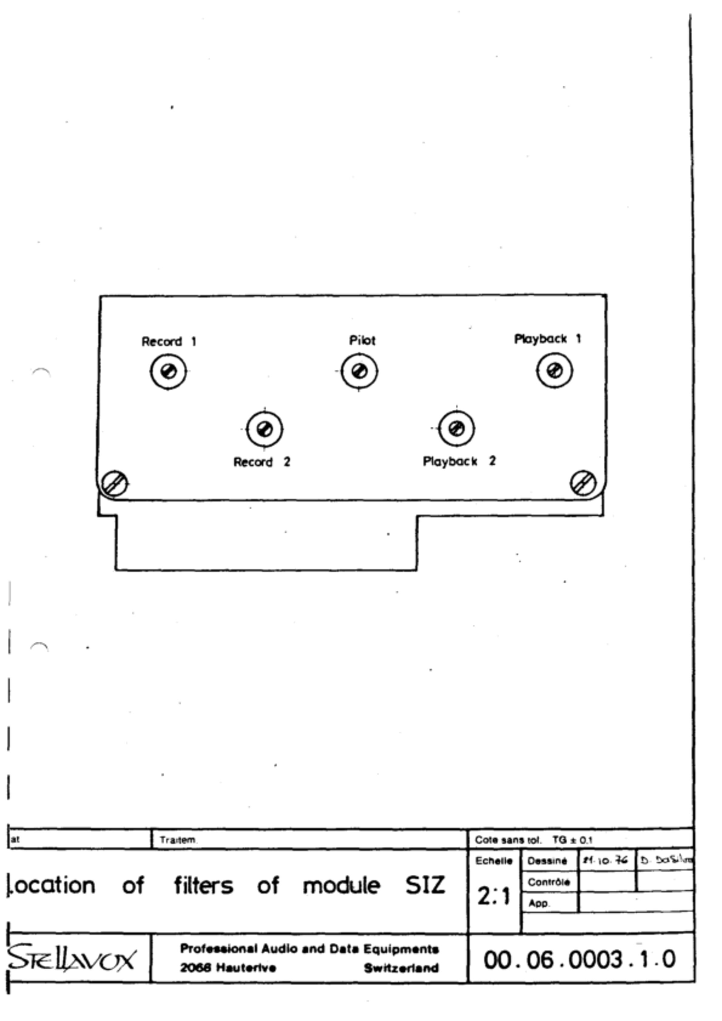
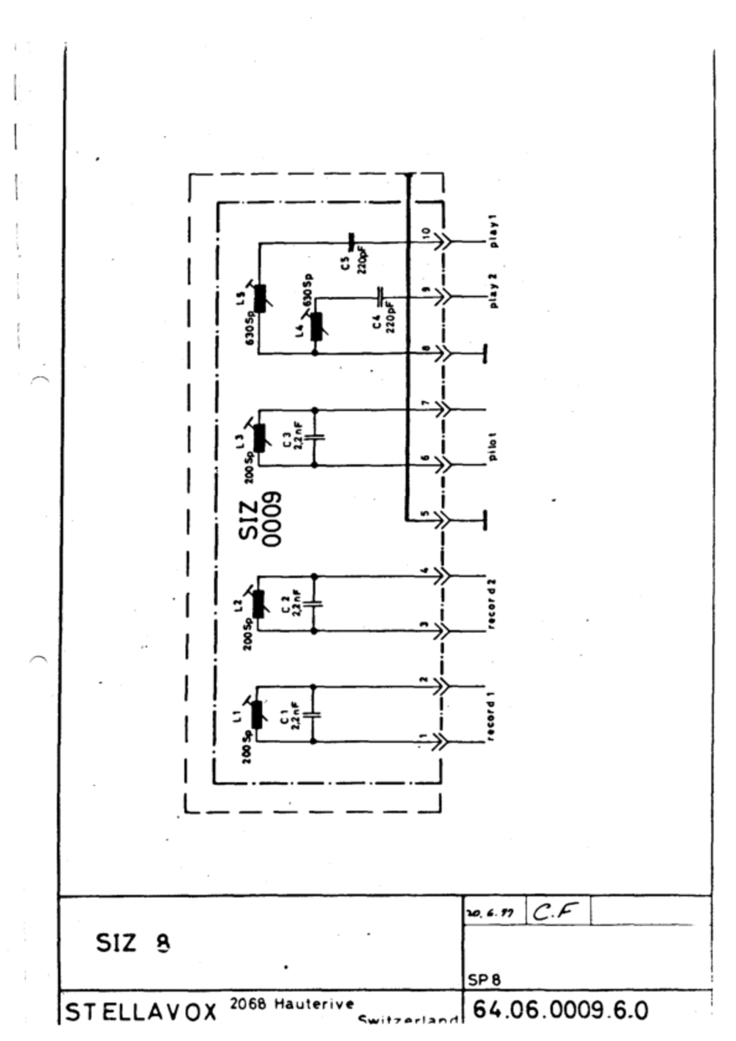
8.5 Filter SIZ
See drawing No, 00.06.0003.1.0. Adjusting of SIZ Filters: remove Rec. module SPC+S0C and in position DIRECT of the switch "Tape-Direct" set on minimum pre-magnetisation rejection during recording. Repeat measurements in position TAPE of the switch.
8.6 Hum Compensation
For compensation of the motor induction on the play-back sound heads, a magnetic coil is wired between the "cold" ends of the head wirings and the 6 V point (ground).
Remove SHD cover and select the optimum solder points compensation.
8.7 Synchromodule SXQ
See under Chapter 7, 7,18 - 7.24.
8.8 Synchromodule SQS

- Set the beep-level with the trimmers (1) on 1.55 V (O dB modulometer) for measurement use either the SP 8 modulometer (pilot function switch on LEVEL position) or the output OUTPUT DIRECT (Pin 2).
- Select the frequency of the crystal-reference-oscillator or 50 or 60 Hz.
- With the trimmer (3) set the reference crystal level on 1.55 V (0 dB modulometer). For measurement use either function switch on position 1N) or the SP 8 modulometer (Pilot output SYNCHRO PILOT OUT (Pin 3).
- Disconnect the trimmer (turn right round to the right).
- Switch the SYNC-switch (4) of ‘the SQS to the position osc (3).
- Record a frequency of 3150 Hz on an audio track, using the flutter-meter adjusted to zero drift.
- Rewind to the start of the recording. :
- Play-back of 3150 signals (output OUTPUT DIRECT - in 2).
- Switch the SYNC-switch of the SQS on position SYNC IN (1).
- Set the speed with the trimmers (6) for zero drift so that by switching from SYNC-IN to OSC and reverse no speed difference results.
- Switch the SYNC-switch on the position OSC (3).
- Set the pilot-playback-level using a pilot-reference tape with the trimmers (2) to 1.55 V. For measurement use either the SP 8 modulometer (pilot function switch in position OUT) or the output EXTERNAL pilot (5).
- Set the pilot-record-level with the 100 k trimmer, which is inside the machine (on the foot of the SIZ modules in machines up to No. 772.320 and below the SWR module in machines from 772.321).
Record the signal 50 (or 60) Hz of the crystal oscillator and rewind to play back the signal. For measurement use either the SP 8—modulometer (pilot function switch on position OUT) or the output pilot EXTERNAL (pin 5). If the signal is weaker than 1.55 V, the record level must be increased and reverse.
- Switch the SYNC-switch of the SQS on position ON (1).
- Control of the synchronisation functions: if the synchro is correct, the front red LED lights up. For those machines equipped with a pilot functions switch, this must be switched to the position CORR. The Pointer on the modulometer must stay on zero.
For an easy check of the SQS the CORR+ pointer must be deflected by braking the left spool with the hand. If the right spool is accelerated, the CORR- pointer must be deflected. For a better check, introduce a reference frequency of 50 or 60 Hz_ 2 % deviation in the synchrosocket and check the function of the SYNC.
Should no flutter meter be available, but however a counter, appropriate instructions are given above under 1 - 15, with the exception of:
6. By use of the signal 3150 Hz, the frequency of the Beep (approx. 1000 Hz) will be recorded.
8. Playback of this 1000 Hz signal.
10. Setting of the speed with the trimmer (6) so that by changing ‘SYNC ON" to "OSC" and reverse the meter shows the same frequency.
Circuit
Block Switching Diagram - No. 63.05.0201.7.0
<<No. 63.05.0201.7.0>>
NOTE this is the SP 7 block diagram
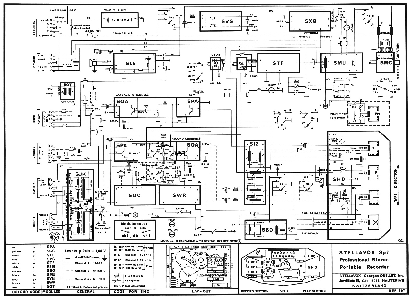
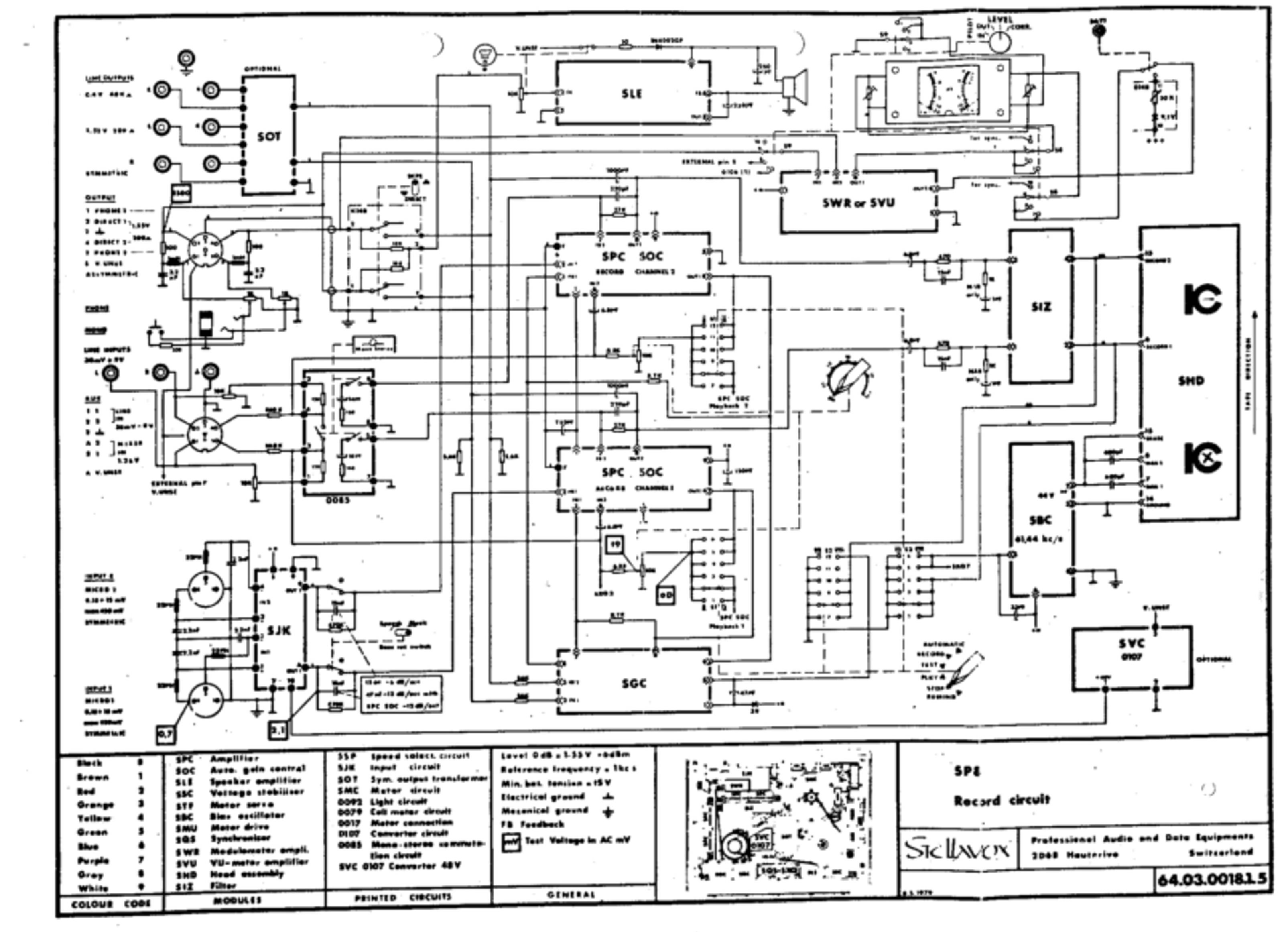
Current Diagram "RECORD" - No. 64.03.0018.1.5
<<No. 64.03.0018.1.5>>
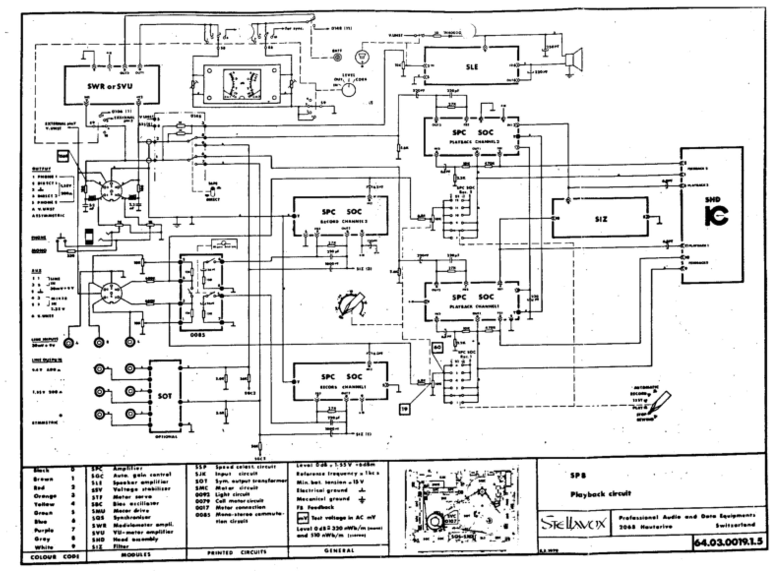
Current Diagram "PLAYBACK" - No. 64.03.0019.1.5
<<No. 64.03.0019.1.5>>
Current Diagram “POWER SUPPLY" - No. 64.03.0016.1.5
<<No. 64.03.0016.1.5>>
Current Diagram "PILOT" - No. 64.03.0017.1.5
<<No. 64.03.0017.1.5>>
SJK 0137 & 0138 - No. 64.06.013[78].1.0
<<No. 64.06.0138.1.0>>
SIZ - No. 00.06.0003.1.0
<<No. 00.06.0003.1.0>>
SIZ 8 - No. 64.06.0009.6.0
<<No. 64.06.0009.6.0>>
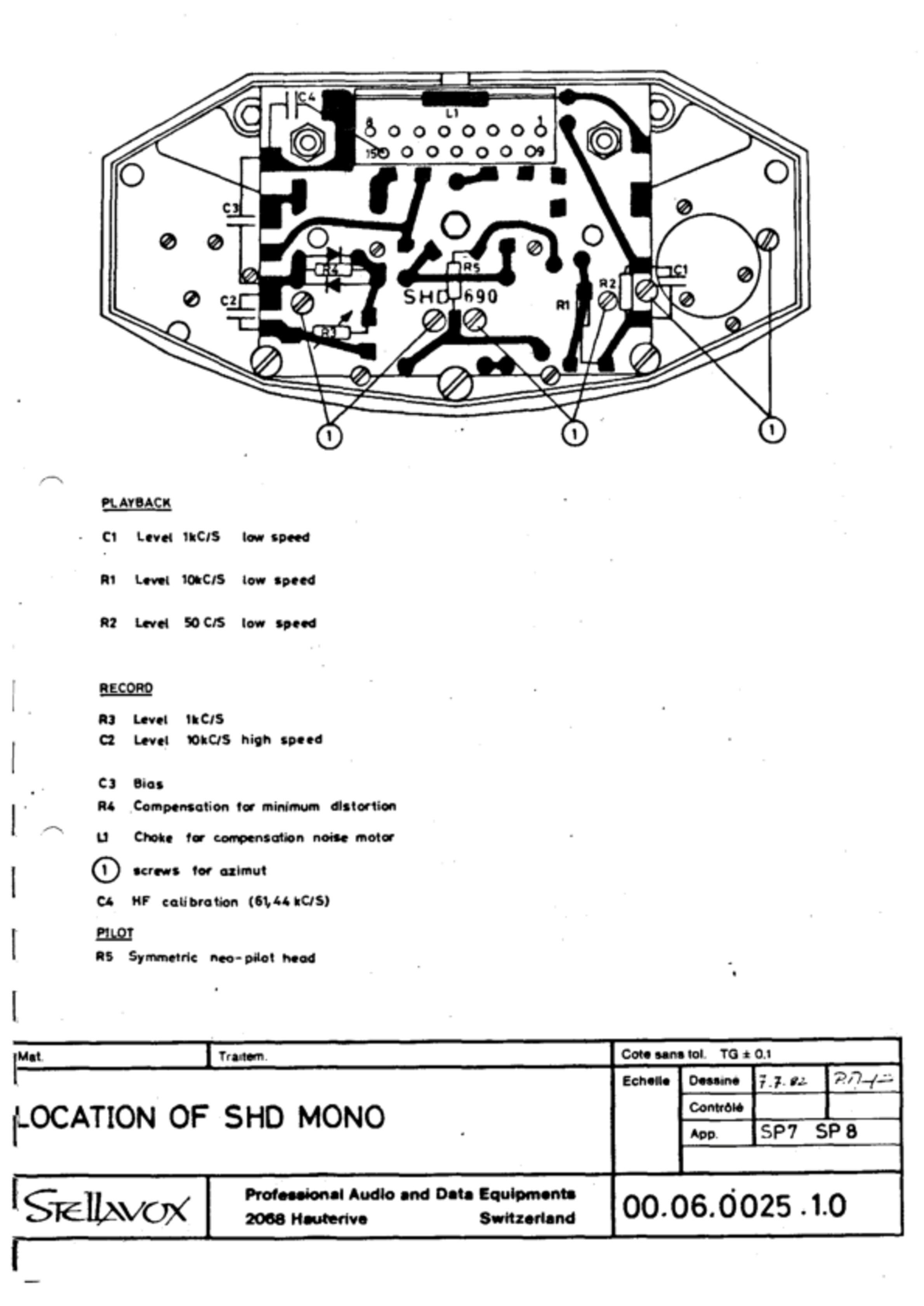
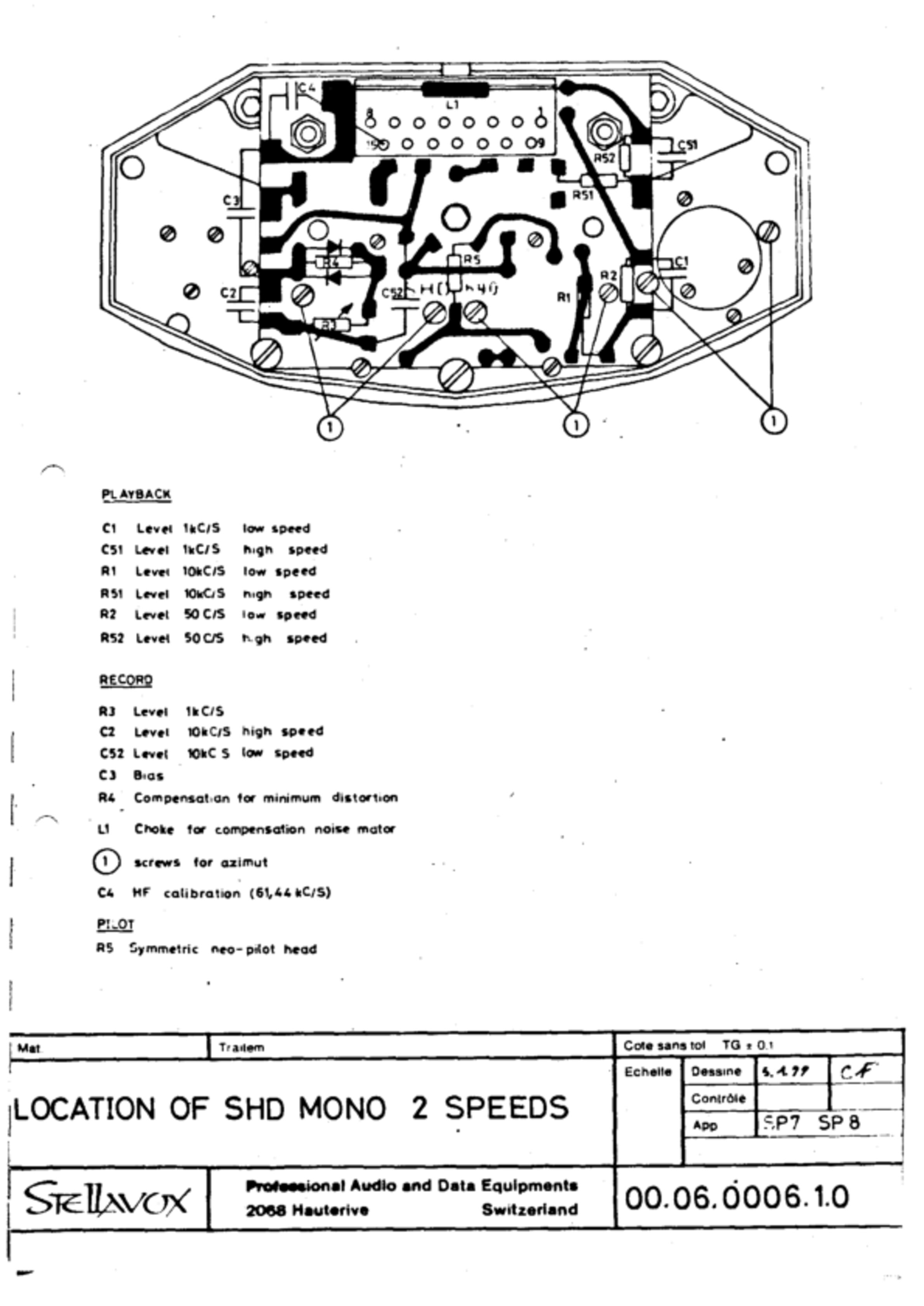
SHD - Mono Head
<<No. 64.03.0023.1.0>>
<<No. 00.06.0025.1.0>>
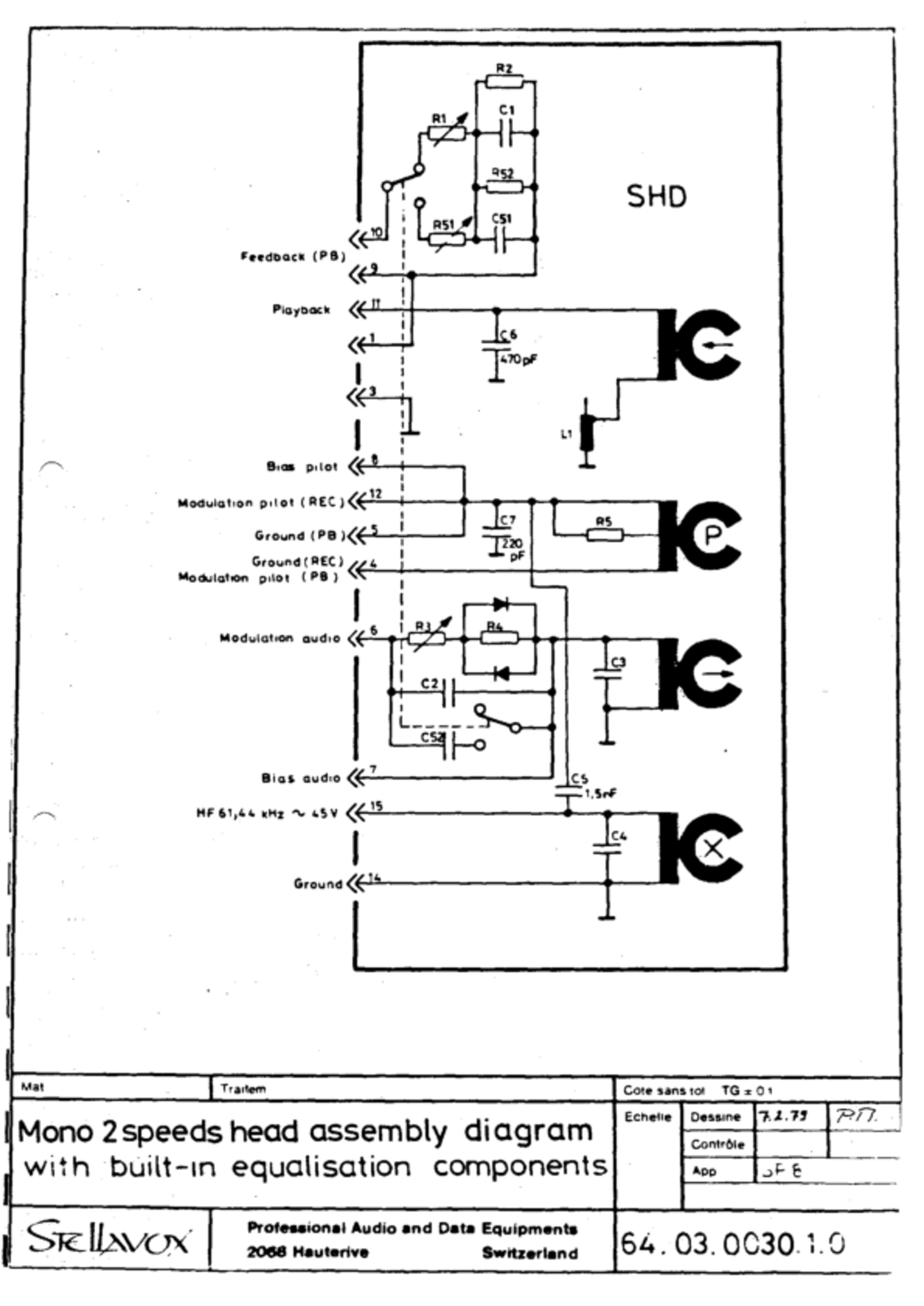
SHD - Mono Head 2 Speed
<<No. 64.03.0030.1.0>>
<<No. 00.0006.1.0>>
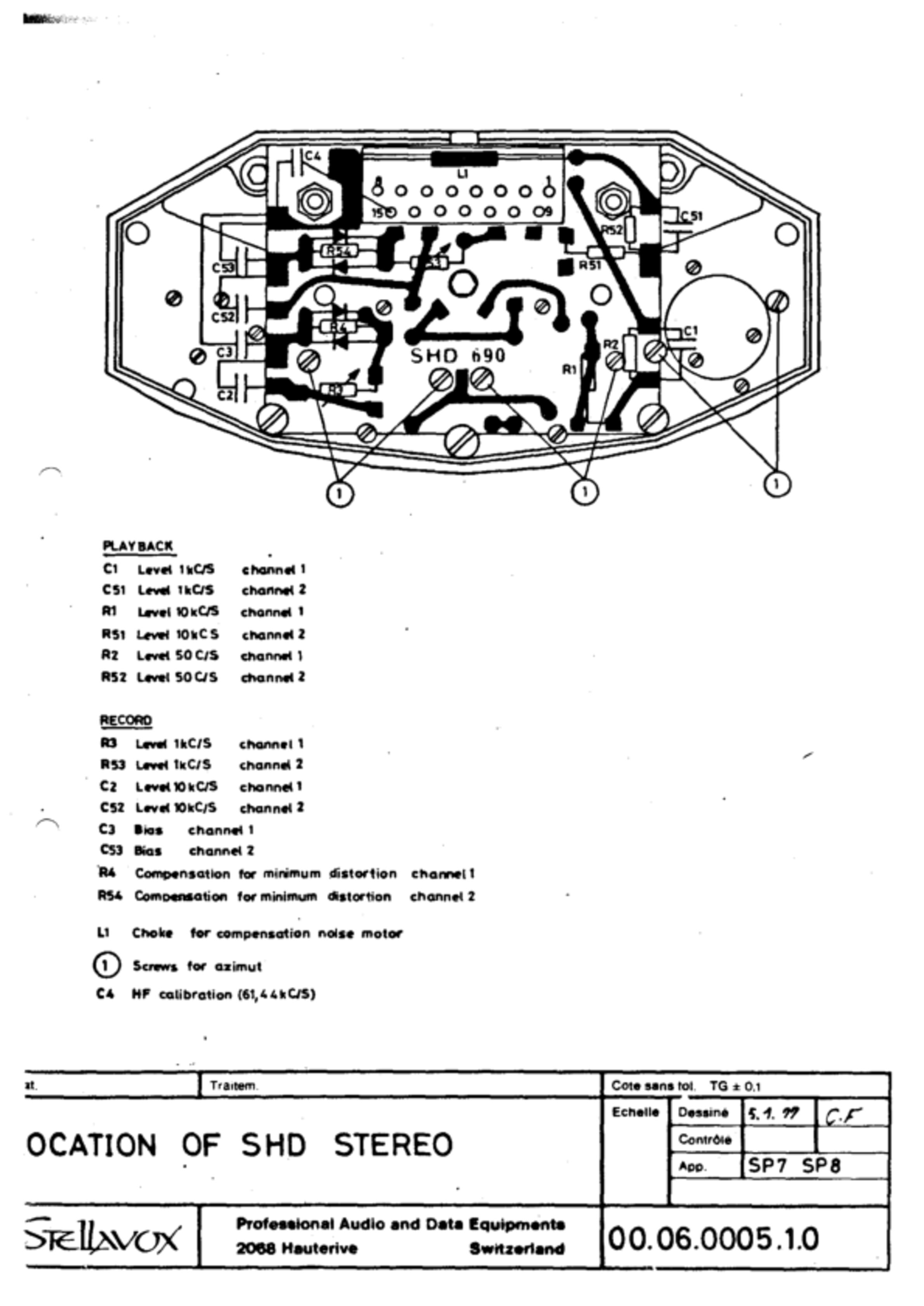
SHD - Stereo Head
<<No. 64.03.0022.1.0>>
 <<No.
00.06.0005.1.0>>
<<No.
00.06.0005.1.0>>
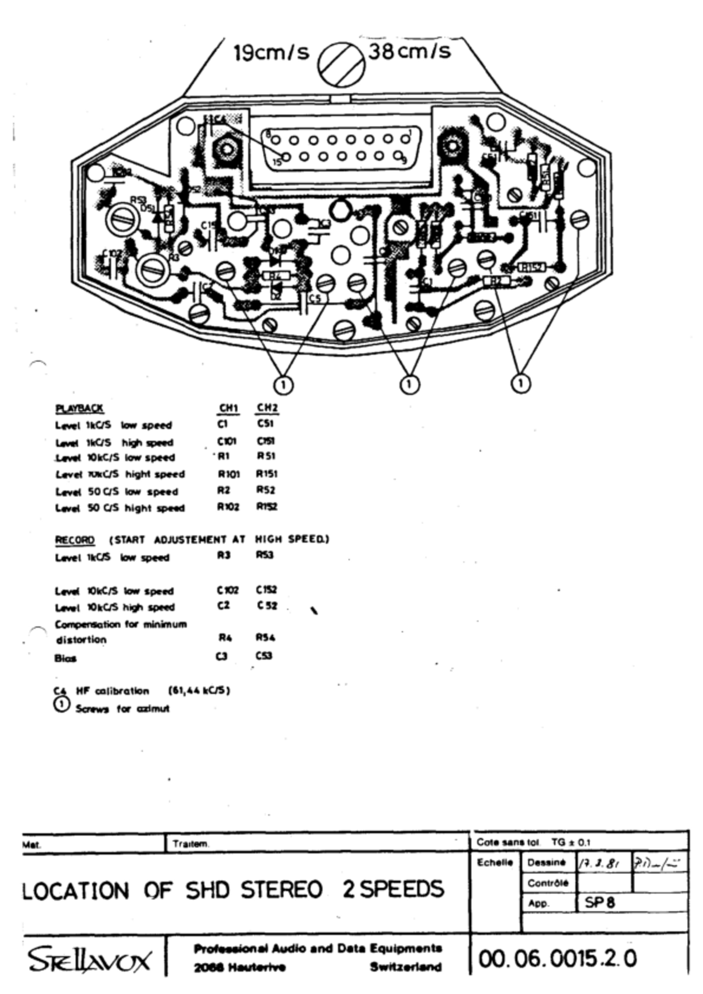
SHD - Stereo Head 2 Speed
<<No. 64.02.0010.1.0>>
 <<No.
00.06.0015.2.0>>
<<No.
00.06.0015.2.0>>
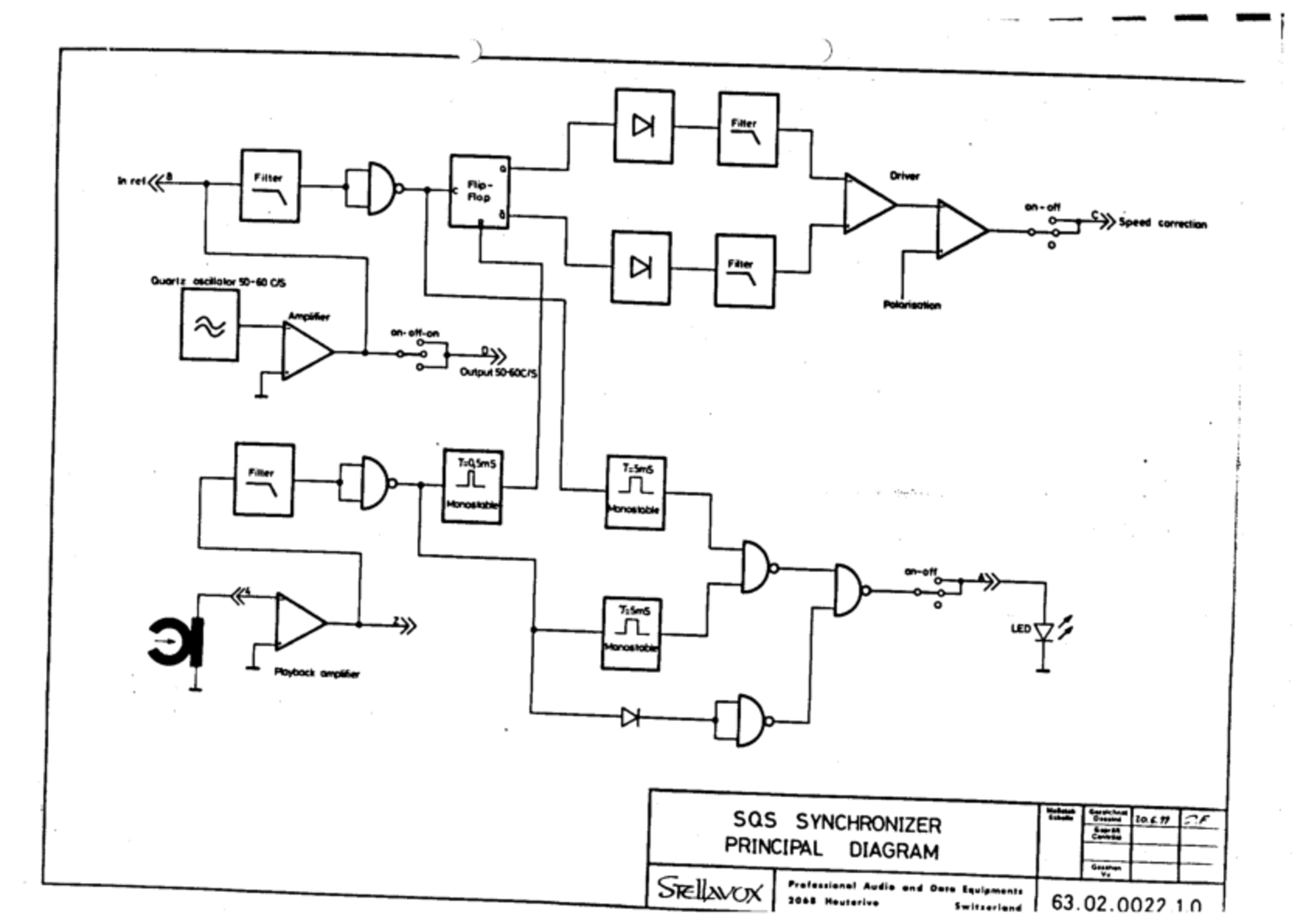
SQS - No. 63.02.0022.1.0
<<No. 63.02.0022.1.0>>
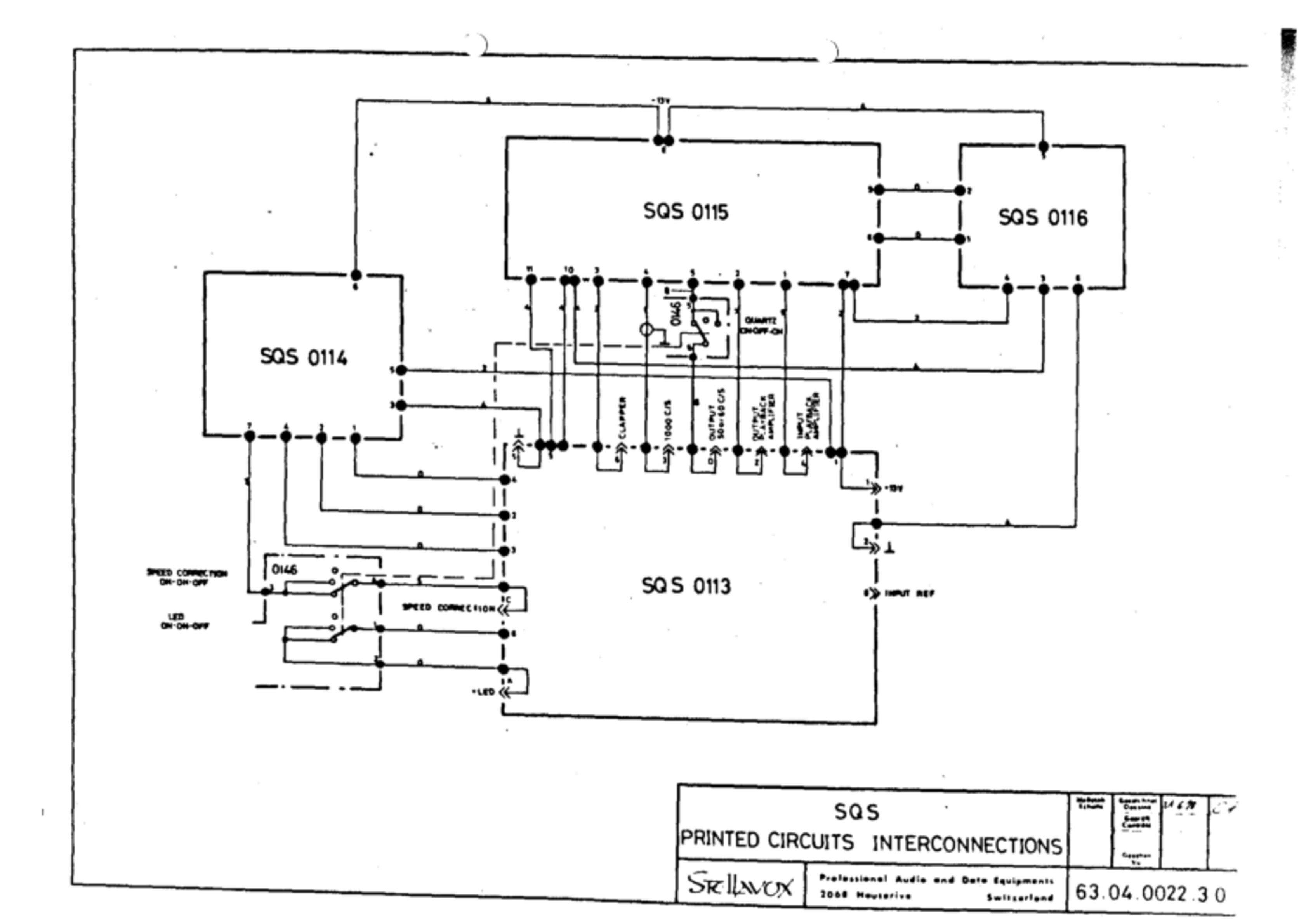
SQS Interconnects - No. 63.04.0022.3.0
<<No. 63.04.0022.3.0>>
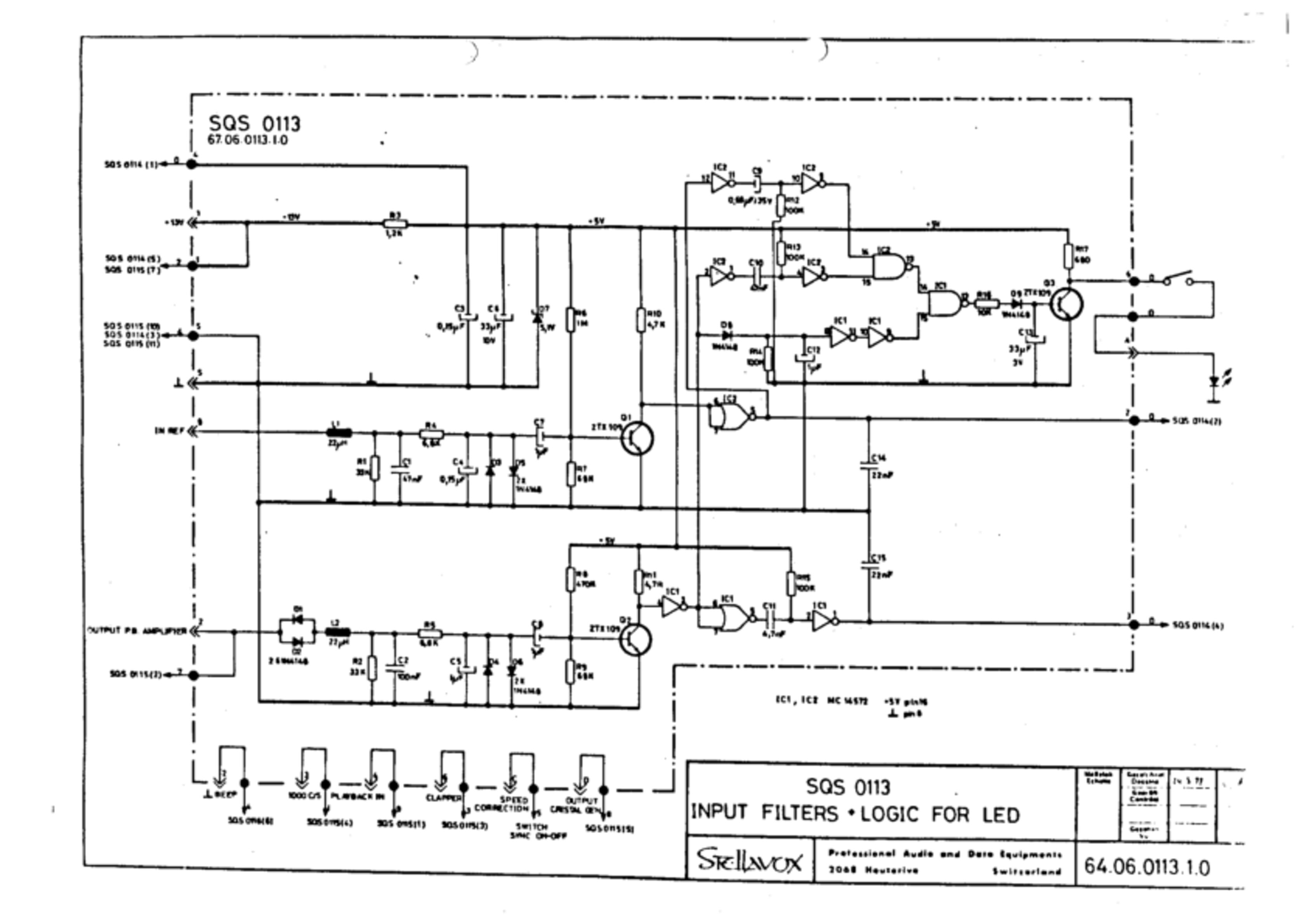
SQS 0113 - No. 64.06.0113.1.0
<<No. 64.06.0113.1.0>>
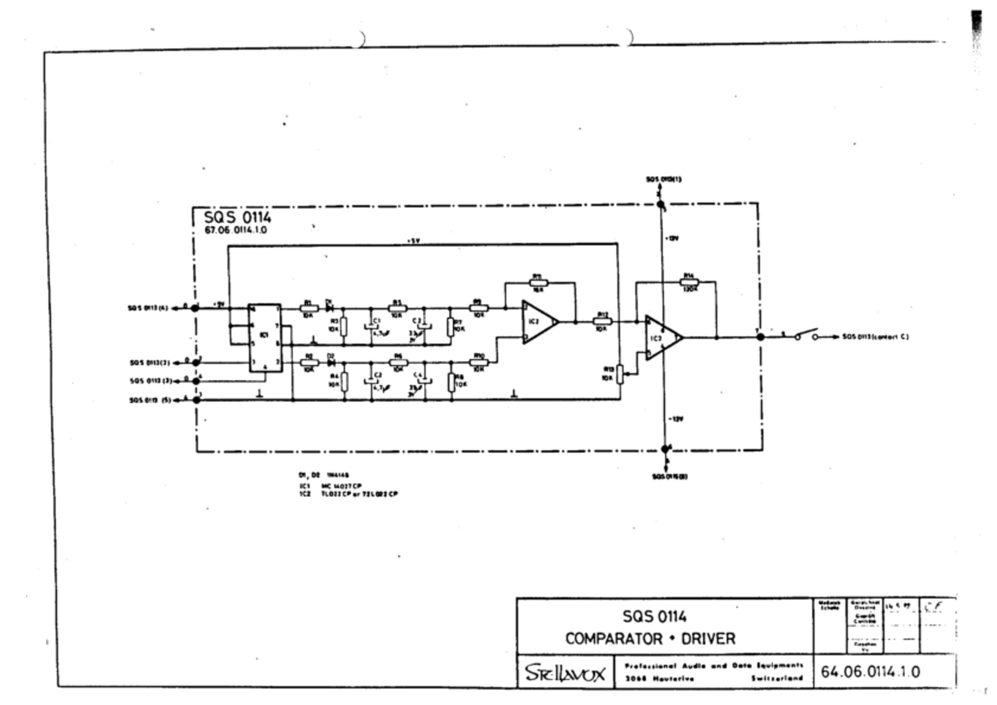
SQS 0114 - No. 64.06.0114.1.0
<<No. 64.06.0114.1.0>>
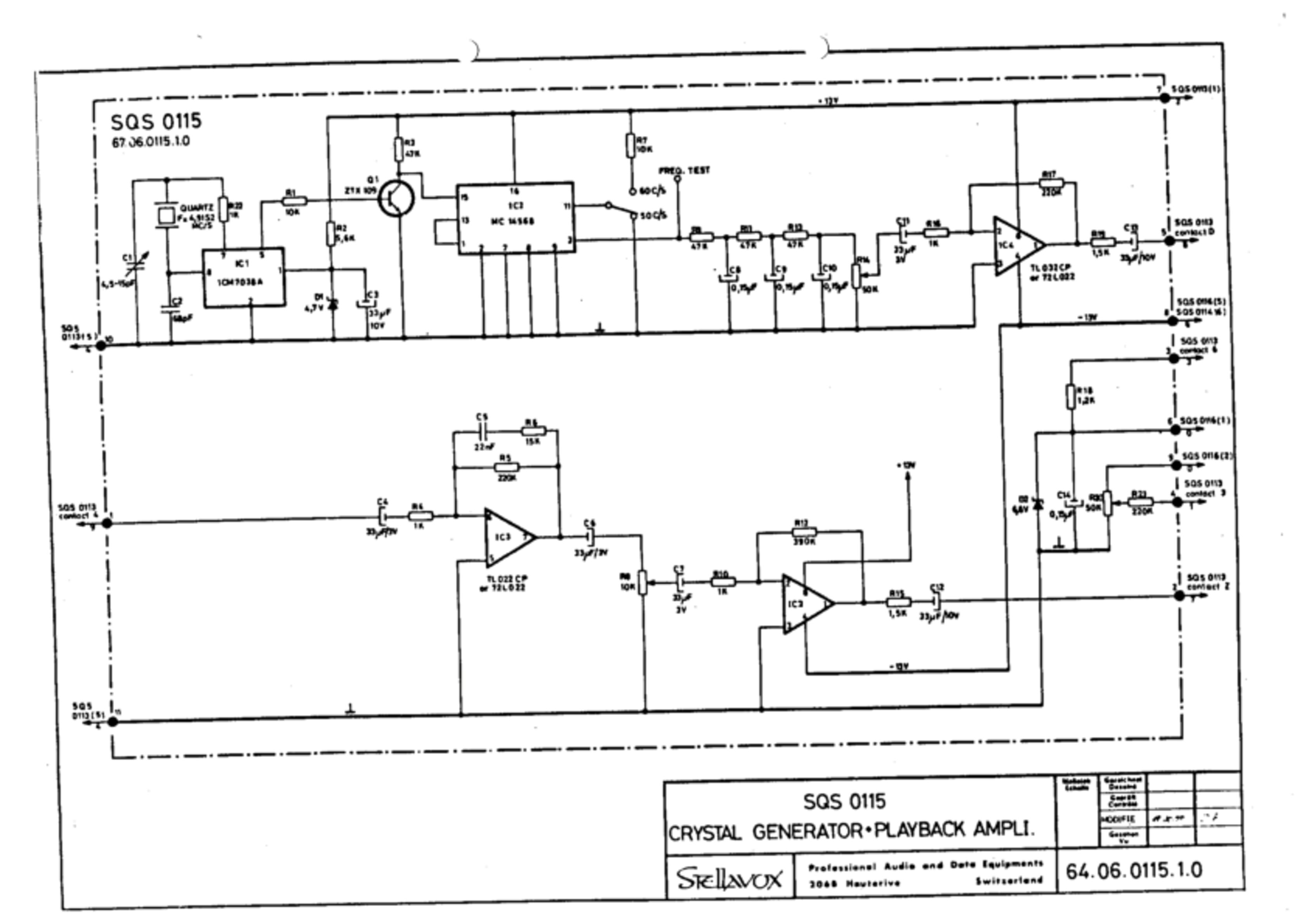
SQS 0115 - No. 64.06.0115.1.0
<<No. 64.06.0115.1.0>>
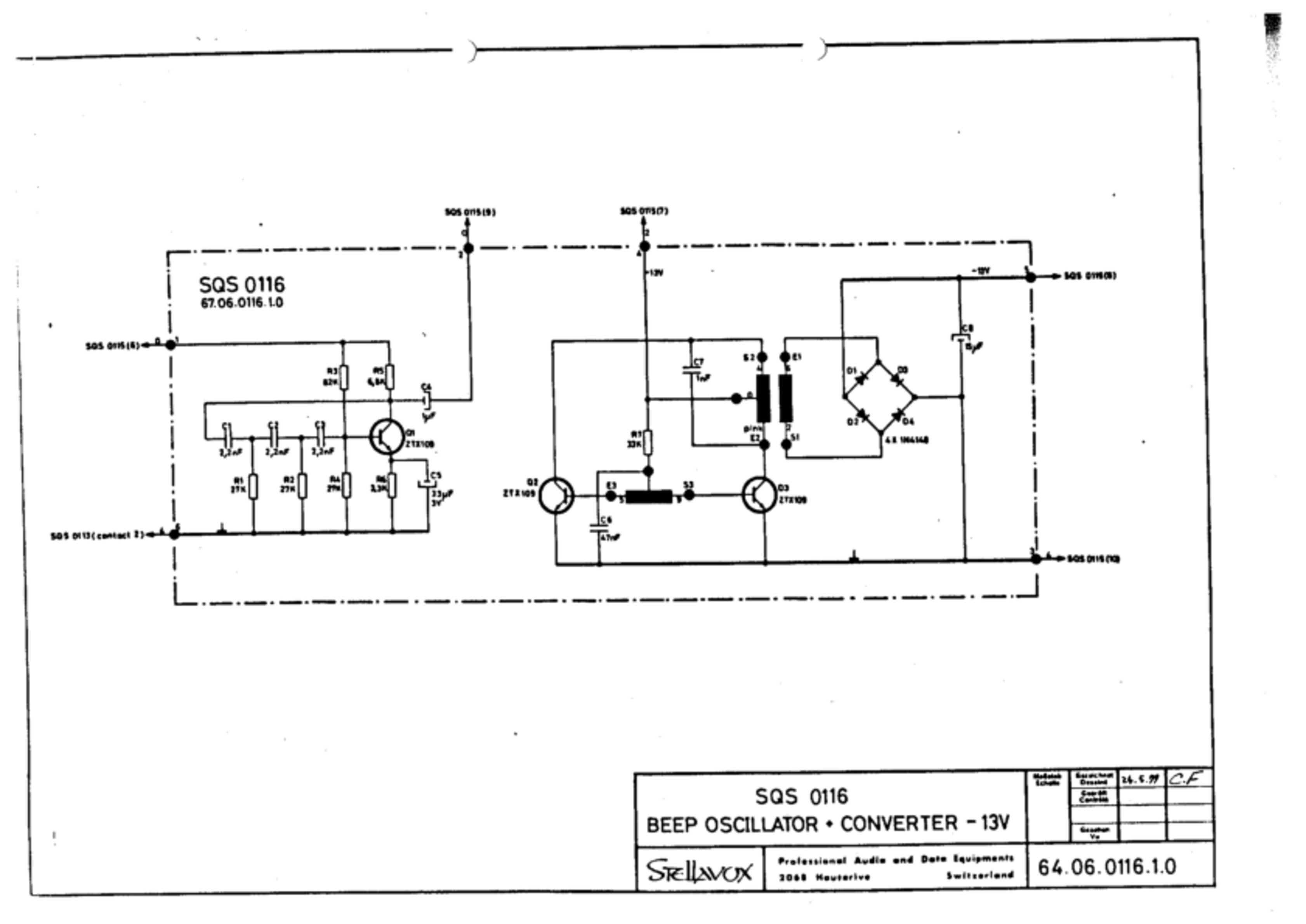
SQS 0116 - No. 64.06.0116.1.0
<<No. 64.06.0116.1.0>>
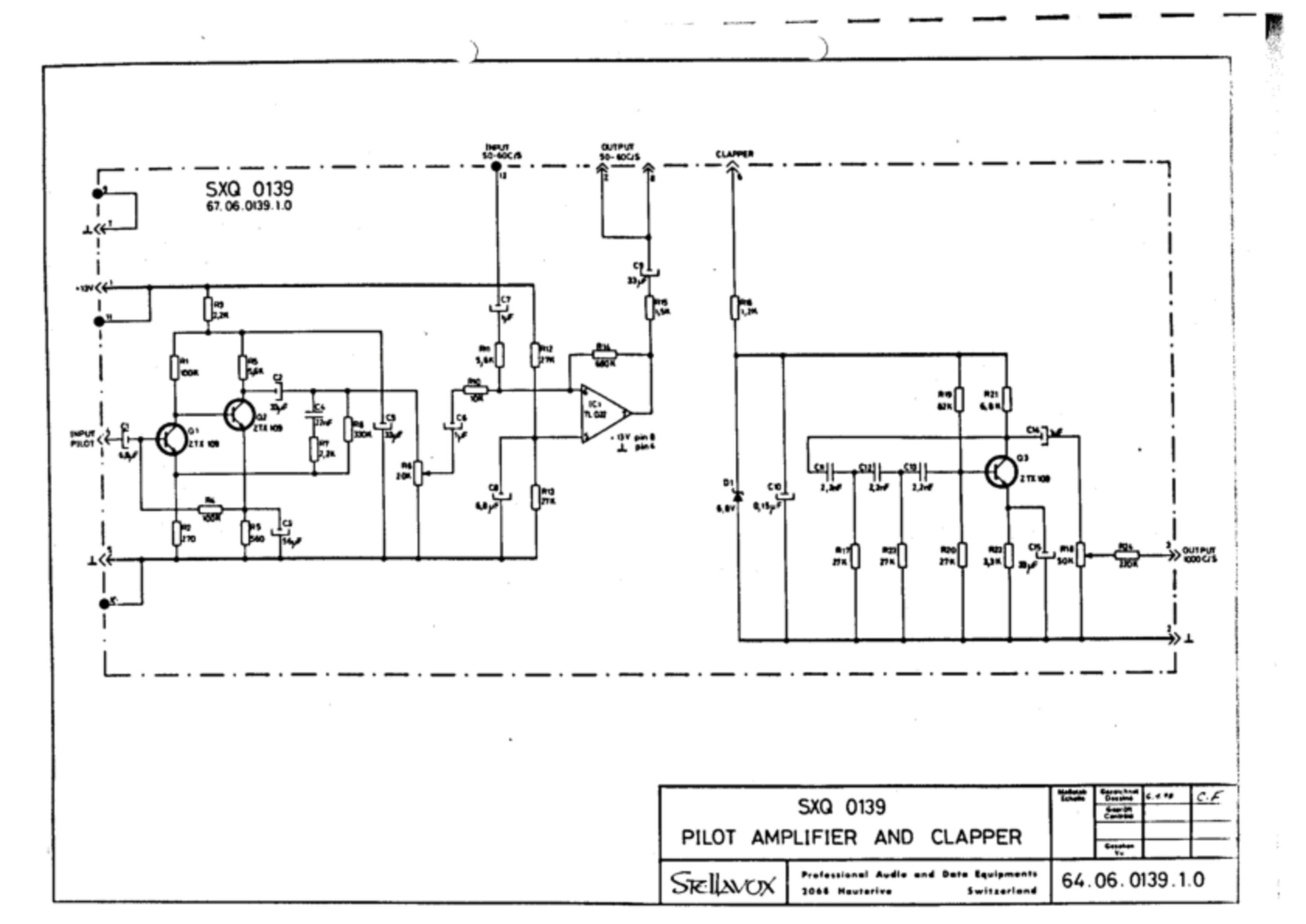
SXQ 0139 - Pilot amplifier and clapper - No. 64.06.0139.1.0
<<No. 64.06.0139.1.0>>
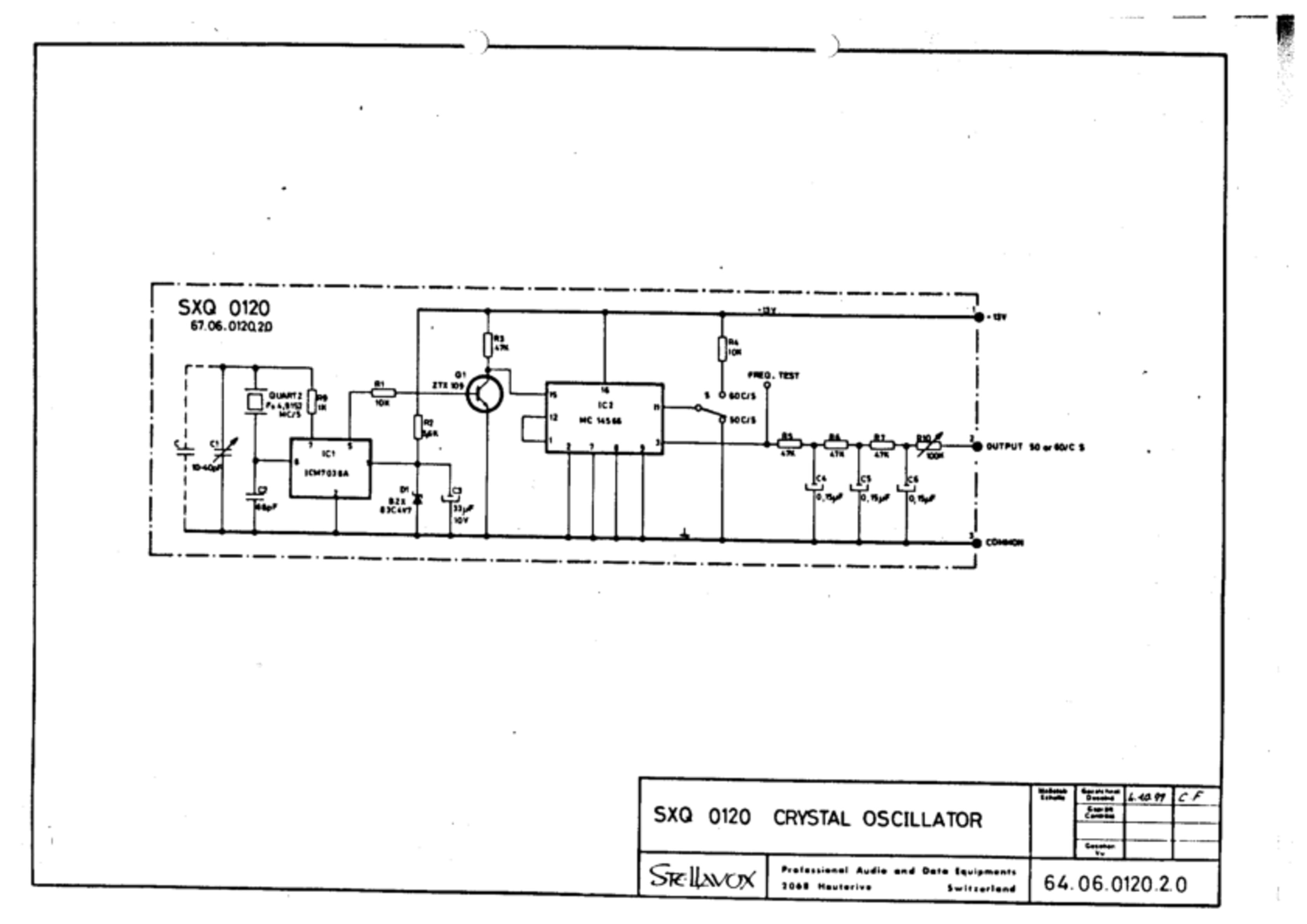
SXQ 0120 - Crystal oscillator - No. 64.06.0120.2.0
<<No. 64.06.0120.2.0>>
Notes
This is an unofficial version of the Stellavox SP8 service manual that has been reconstructed from notes, scans and partial transcriptions in the hope it may be useful. There are almost certainly transcription errors, missing data and unreadable 1bit diagrams…
Any corrections, additions or comments → https://github.com/zzkt/stellavox